Despite appearances (i.e., no posts for years!), I have been making steady if grindingly slow progress on this project. The reasons for this are a combination of other distractions (e.g. interesting jobs, moonlighting as a jazz musician - my other occupation - and having a young child), and my stubborn insistence on making every aspect of this project myself, which in turn has meant reconditioning my lathe, learning to use the CNC milling machine I bought myself, and so on.
Anyway, I plan to provide a quick overview of progress to date here, and then dig into some of the details in future posts. So, what's been happening? Three main things: Choosing the electronics platform for the project, designing and building the mechanical components, and interfacing the electronics to the control software.
Electronics
After a brief flirtation with the Beaglebone Black, I had some exposure to an STM32-based controller for a haptic robotic controller at my then employer (Generic Robotics), and realised that it provided all the functionality I needed and seemed pretty straight forward to develop for. Consequently I selected a STM32f746 mbed development board which includes an Ethernet interface, hardware timers for incremental encoder quadrature, tons of processing power, and furthermore is absurdly cheap. I'm using the mbed environment to develop on, which brings with it lots of rich libraries including an easy to use TCP-IP stack. On top of that I designed a simple breakout board to hook up my three incremental encoders (one per DOF), and do some level shifting.
I'm using an Electrocraft brushed DC servo which I had spare from an old CNC project, complete with 500 line encoder, and two AEDC-5560 5000 line encoders for the two pendulum axis.
For a DC motor, torque is proportional to current, so I'm using a Maxon Escon 50/5 controller module (that's 50V, 5A maximum) with an integrated current control loop. I just have to feed it a PWM signal or analogue voltage proportional to the target current, and it will do the rest.
Mechanical design
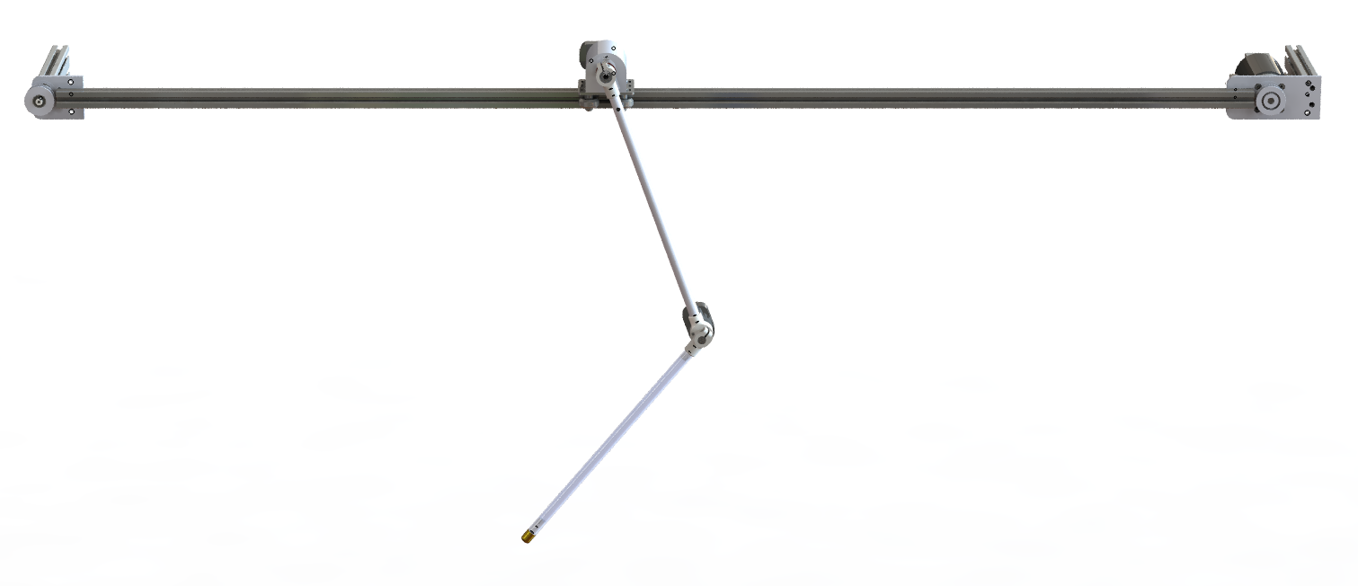
This definitely deserves its own post, but I'll try and summarise the system briefly. I'm using V-Slot bearings and 1.5m long extrusion for linear motion of the cart. The cart itself is a piece of V-Slot standard plate with a custom designed body which holds the bearing assembly, encoders and slip ring. A loop of GT2 timing belt provides mechanical power transmission, and two custom machined plates hold the servo and timing pulleys. Short lengths of aluminium extrusion bolted to the two plates allow the whole assembly to be quickly clamped to a bench when I want to work on the project.
The pendula are made from 12mm (10mm ID) aluminium tube. At each end are a pair of brackets which hold bearings and clamp onto the respective axles. There's an encoder on the back of each joint. The second encoder, between the two pendula, is wired via a through-hole slip ring on the back of the cart. Each joint consists of a machined aluminium axle supported by two deep groove ball bearings.
Control interface
I had wanted to rewrite the Matlab based controller to run on the STM32 development board, the idea being that I would transfer the nominal trajectories from the Matlab-based trajectory optimisation program to the controller, and then run the system independently of the host PC. Although this would be an interesting exercise, I realised that it's just a whole chunk of extra work, and the project is going slowly enough as it is! So instead I'm interfacing to the controller using UDP over Ethernet. I can achieve an update rate of up to 2 kHz using this approach. Unfortunately the in-built ethernet functions in Matlab seem to be extremely slow. So far as I can tell they open a new socket for every packet sent, which seems absurdly inefficient. In the end I found some example code for a compiled MEX ethernet interface that offered much higher performance, and I modified it to suit my purposes. I'll dig up and post a link to the original code soon, and my own if I can make it presentable.
-----------------
What next? All of the above works, even if there's scope for improvement. I've started measuring the physical properties of the system, e.g. moments of inertia, joint damping, cart damping, etc, and I've begun running trajectories on the system, and using the trajectory optimisation library to generate trajectories using a model of the system using these parameters. I haven't swung the pendulums up yet, but I'm getting closer. More soon!
Thanks for reading.
Discussions
Become a Hackaday.io Member
Create an account to leave a comment. Already have an account? Log In.