 willbaden
The Z axis deviated from using the motors used on the X and Y axis. Instead a motor that was pulled from some random copy machine was used. The linear guides are some that were bought off of ebay coming from China. Not sure if I will go this route for the next generation of cnc anything, but for a cheap route, they work.
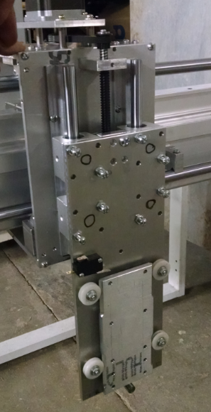
The lead screw is two start 10 tpi. Which means the lead is 5 tpi. The plasma gun attaches to a floating head the rides on some plastic bearings that was pulled from (I think) a typewriter. The edges of the plate were chamfered to create a peak that would right in the v notches of the plastic bearings. Located at the center of the floating head, stroke was limited by a hard stop captured inside of a slot.
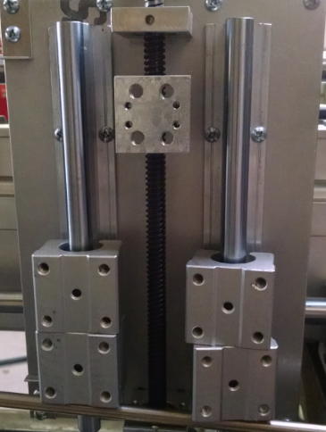
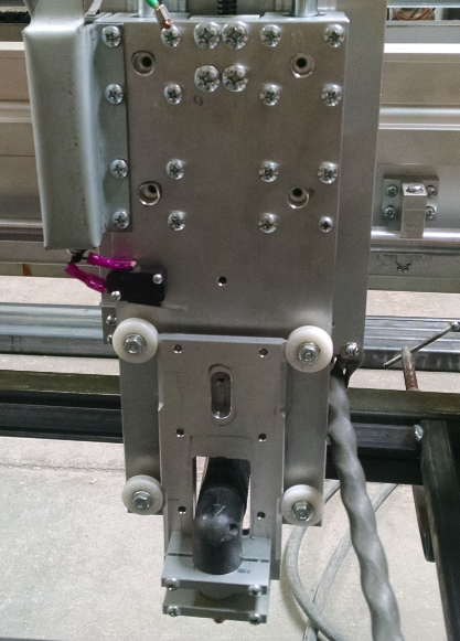
The Z axis plate was removed exposing the linear guides.
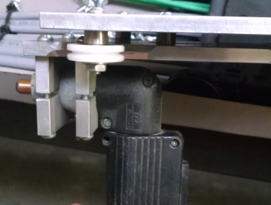
The plasma mounting was looked over.
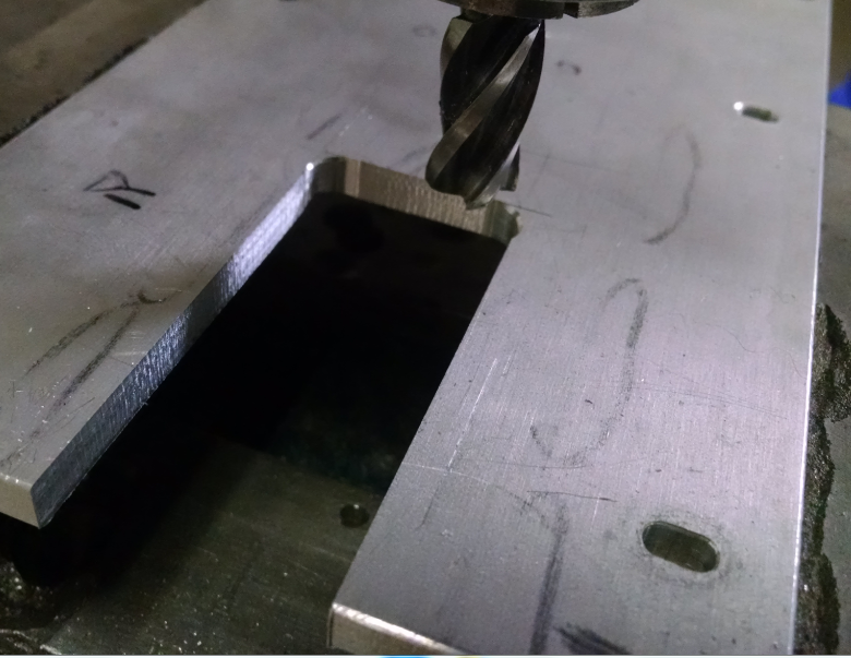
The hard physical limit (not switch) will have to be moved up 2 inches and the plates will need to be slotted to allow for the handle to stick underneath the carriage. Starting with the main plate, the corners were drilled and a band saw rough cut the material out. An end mill in the mill/drill brought the slot to size.
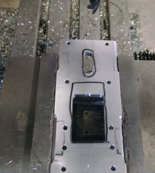
The floating head plate then needed similar treatment. The hard stop slot was shifted up 2" and a 2"x1.25" slot was added.
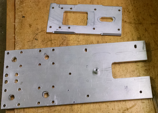
And the finished parts ready for assembly:
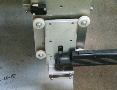
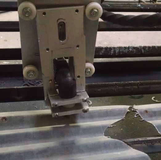
The parts were assembled to try fit the plasma torch floating head travel. The mechanical limit hits before the torch itself hits the slots edges.
So far so good. This assembly was then placed onto the linear guides and travel was tested. The screw head on the back ended up hitting the lower lead screw bearing. So the screw hole was counterbored until the travel was unlimited.
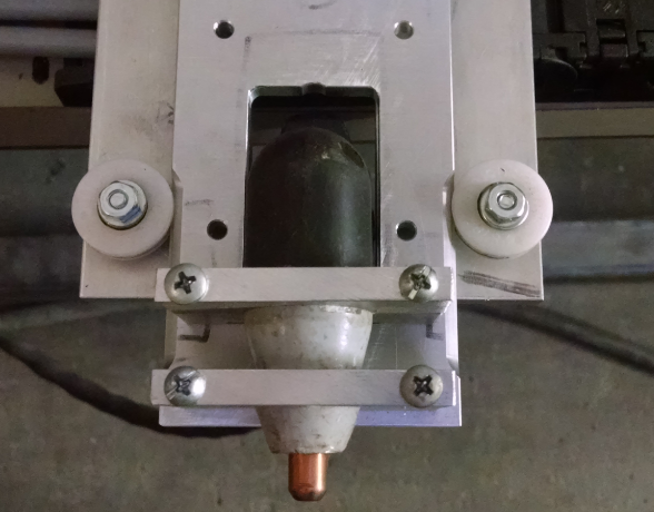
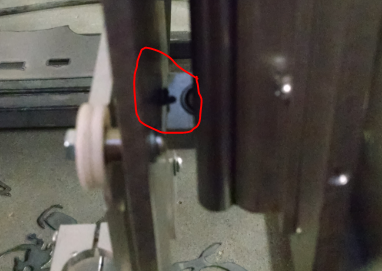 The cable for the torch was the next concern. It had to stay out of the x axis travel from being pinched. Some aluminum cable clips were modified to fit. The picture below shows them on the left and right.
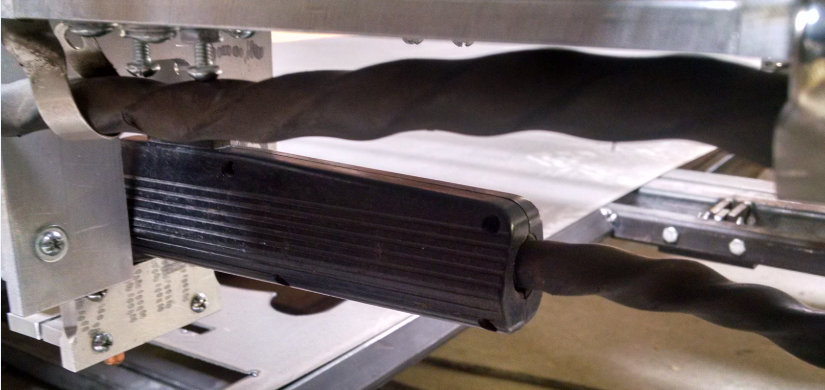
And the completed modification:
10/2/16
Floating Head Crash. After successfully cutting a part out of corrugated tin, I wanted to cut the exhausted material from the larger sheet to continue cutting other parts. The Torch was sent in rapid over to the cut location and caught the corrugated tin that was clamped to the table. This popped the floating assembly out of the tracks. cracking the upper left v groove.
The screws were loosened and the assembly remounted. Even there is a cracked v groove, it still functions. There is definitely a need to standardize what coordinate system does what. Possibly:
- G54 - use for material cut. This will locate the x y cut locations.
- G59 - use as table home location for x and y.
Can then raise the torch to z -1 height (top of the stroke is 0) when traveling between cuts.
So something like this:
- G59 home machine on startup and as needed if there is assumed missed steps
- Move to xy zero of cut using G91 incremental mode
- G54 zero out x y location to new location using G10P0L20X0Y0
- Make cut (Start up part program)
G59G92.1 (to cancel coordinate offset) raise to z 0G54move to next location within part program- At end of program, G92.1 to cancel last coordinate offset.
- Stop Part Program
Will have to look into CamBam - MOP to setup routine in the post processor.
Discussions
Become a Hackaday.io Member
Create an account to leave a comment. Already have an account? Log In.