 Max.K
Max.KAs explained in an earlier project log, the watch was at a point, where it only needed 2 μA in standby mode. Then screen burn-in started showing up and the watch stopped after only a couple of days.
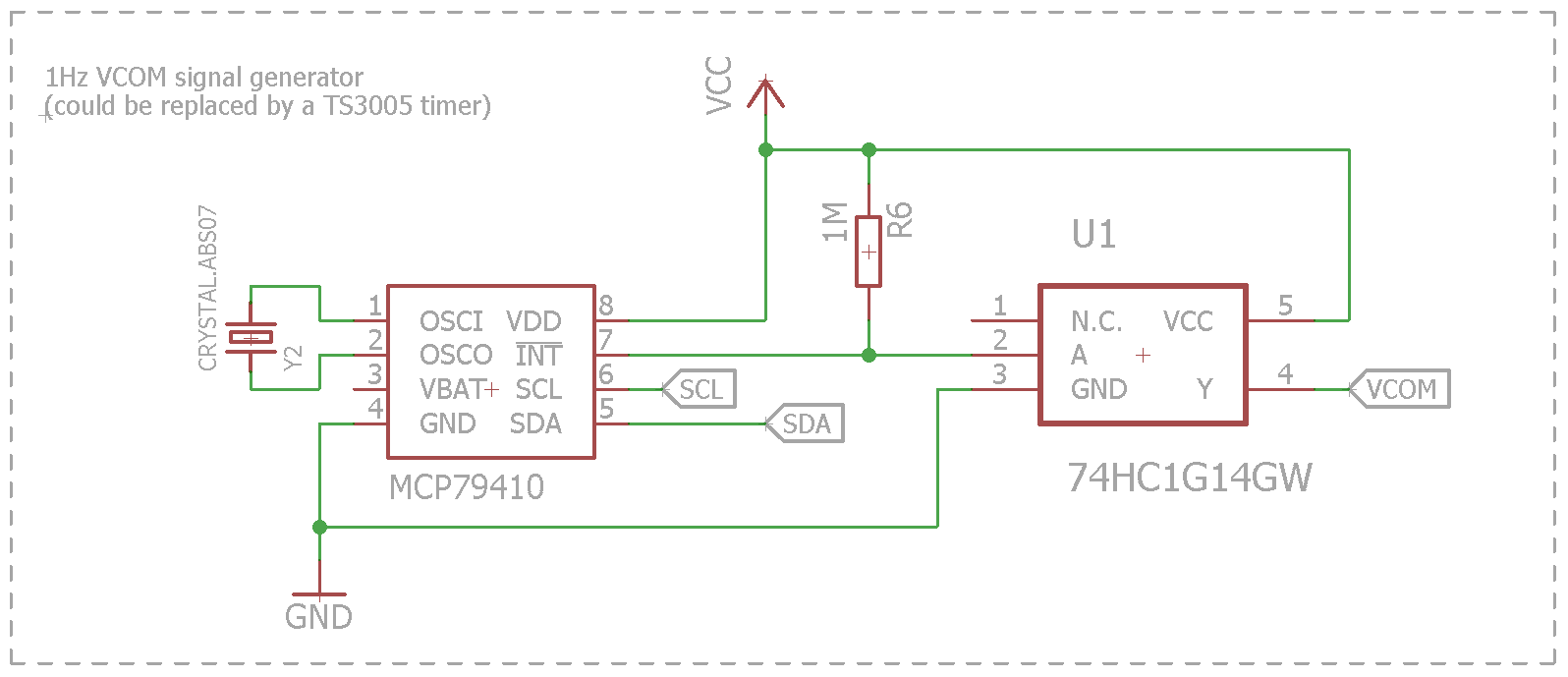
After checking the display's datasheet and application note (http://www.sharpmemorylcd.com/resources/programming_memory_lcd_app_note.pdf) once again, I found a detail I had missed completely: Although the display does not need constant updating, there is a VCOM inversion signal that needs to be generated. "VCOM is an alternating signal that prevents a DC bias from being built up within the panel", meaning that burn-in will occur if the signal is not supplied. The signal can either be generated by software(which the Adafruit library already does) or by a dedicated input pin (EXTCOM). Also a short pulse is not enough, the display needs a 50% duty cycle square wave with a frequency of at least 1 Hz. This was a major problem, because the low power consumption of the watch relied on the Atmega being in standby most of the time. Waking it up every second to toggle a pin would decrease battery life dramatically, which had been the main advantage of this project. Generating the signal by software would not work without the Atmega waking up, so it had to be supplied over the EXTCOM pin. A 1 Hz square wave can't be too hard to generate, or can it?
As it turns out, it can be if you are limited to a few μAs of current and a tiny watch to fit in. The easiest approach would be a 555 timer with some passive components. Although there are hundreds of variations of this chip, I could not find a single one with less than 50 μA of operating current. In the Arduino forum, a schmitt trigger oscillator was suggested to me (http://forum.arduino.cc/index.php?topic=400656.0). The Schmitt trigger itself and the oscillator you can build out of it are explained in detail on Talking Electronics: http://www.talkingelectronics.com/pay/BEC-2/Page49.html. It is basically an inverter with hysteresis than you can use to make an oscillator. At first the idea looked very promising. I got a square wave out of a Schmitt trigger inverter (74HC1G14GW), a 10 MOhm resistor and a 0.1 μF capacitor.
But the problem was again the power consumption. The current draw was varying but at hundreds of μAs. Although the Schmitt trigger usually only draws 10 μA, according to the datasheet there is a delta-current of up to 500 μA, which is needed if the input voltage is in between 0 and VCC. This means, if you are at 3.3 V, the inverter will output 0 V and only draw 10 μA. But if you are at 1.3 V for example, the operating current will be much higher.
Another solution was using a real time clock to generate the signal. Most RTCs have an output pin for a 1 Hz square wave. The DS3231 has such a pin as well, but this feature cannot be used while also having the 1 minute alarm running. There was no way around a second RTC. I didn't want to use another DS3231, because they are relatively expensive at about 8 €. I found the MCP79410 from Microchip, which had a low operating current and the features I needed for only 1 €. Then I made a second PCB revision including the new RTC and fixing some errors from the first version.
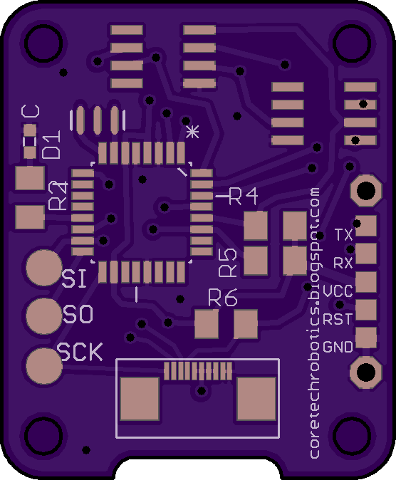
The second revision also includes the DS3231 in a smaller package and moves it to the top side, making room for SMD buttons. Also I switched to the improved programming interface. The traces were still all over the place.
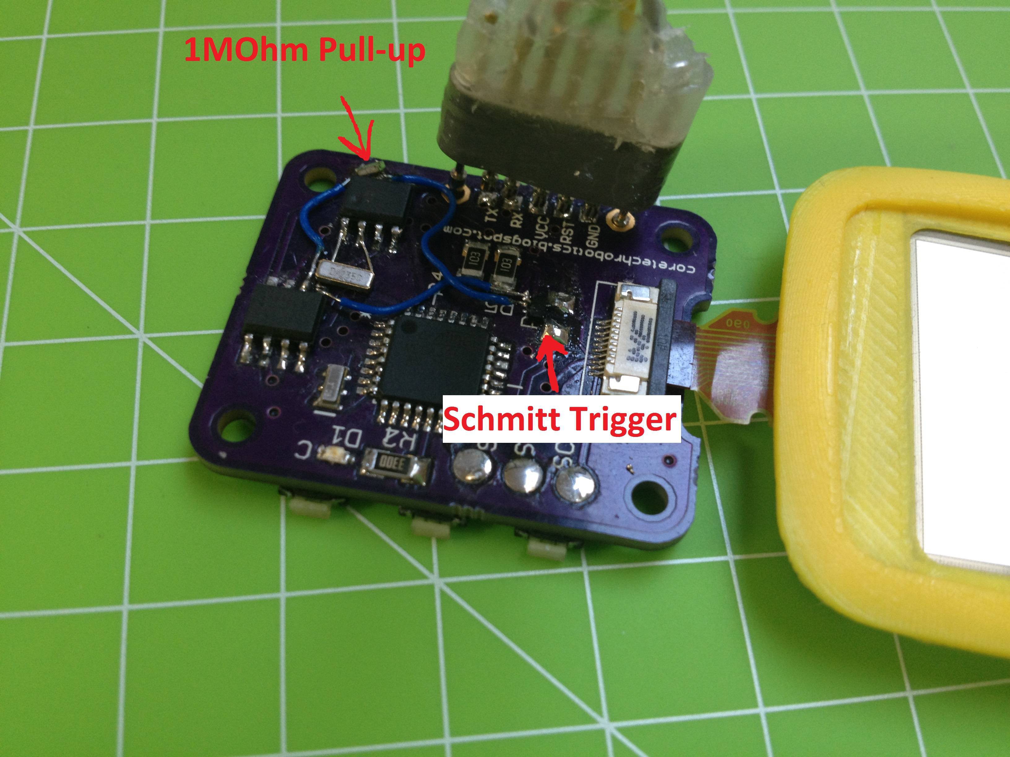
As I wanted to get the project done quickly, I made a lot of errors in the process. One was that I forgot to include an oscillator for the MCP79410. I fixed that by soldering an SMD oscillator directly to the pins. Luckily no additional capacitors were needed. The 32.768 kHz output of the DS3231 can't be used instead of the oscillator because that pin is open drain. With this high frequency you would need a small pullup resistor, which draws too much power.
I got the MCP79410 to work at only 2 μA, which was another small success. Still, getting the 1 Hz signal to the display was difficult. Because the RTC's 1 Hz output is open drain, a pullup resistor is needed. While the signal is low (50% of the time), the resistor is shorted and will draw current. At 10 kOhm this would already be 165 μA on average. Because of that I didn't want a value smaller than 1 MOhm (1.65 μA). While the signal worked with the 10 kOhm resistor and the display stayed clear, with the bigger resistor the burn-in reappeared. My first guess was that the 50% duty cycle requirement of the signal was not met. I tested this by hooking up an Arduino and simulating a 80% duty cycle. The VCOM inversion still worked. The signal is even visible on the display as a tiny black frame pulsing around the display. The problem seemed to be caused by the slow rise time of the signal. Because of the large pullup resistor and the capacitance of the trace it takes some time for the signal to get into a high state. I fixed this with a Schmitt trigger inverter, which I had lying on my desk from the previous experiments. By feeding the slow signal into the inverter, it gets inverted (obviously), which doesn't matter to the display and it gets a more defined faster rising edge.
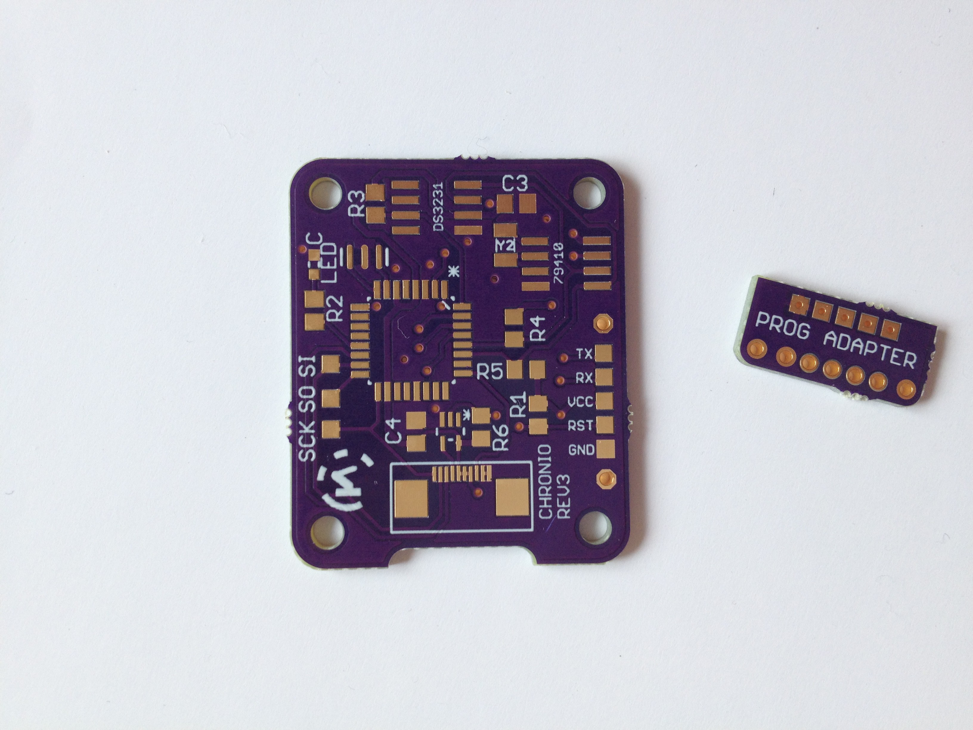
I soldered the new parts on a PCB and it worked fine even with the 1 MOhm resistor! The power consumption is varying between ~2 μA and ~20 μA. Because of this, it was hard to calculate the battery life precisely. I ended up making a third PCB revision including all the improvised changes and fixing every error that was left. Even the traces look nice now:
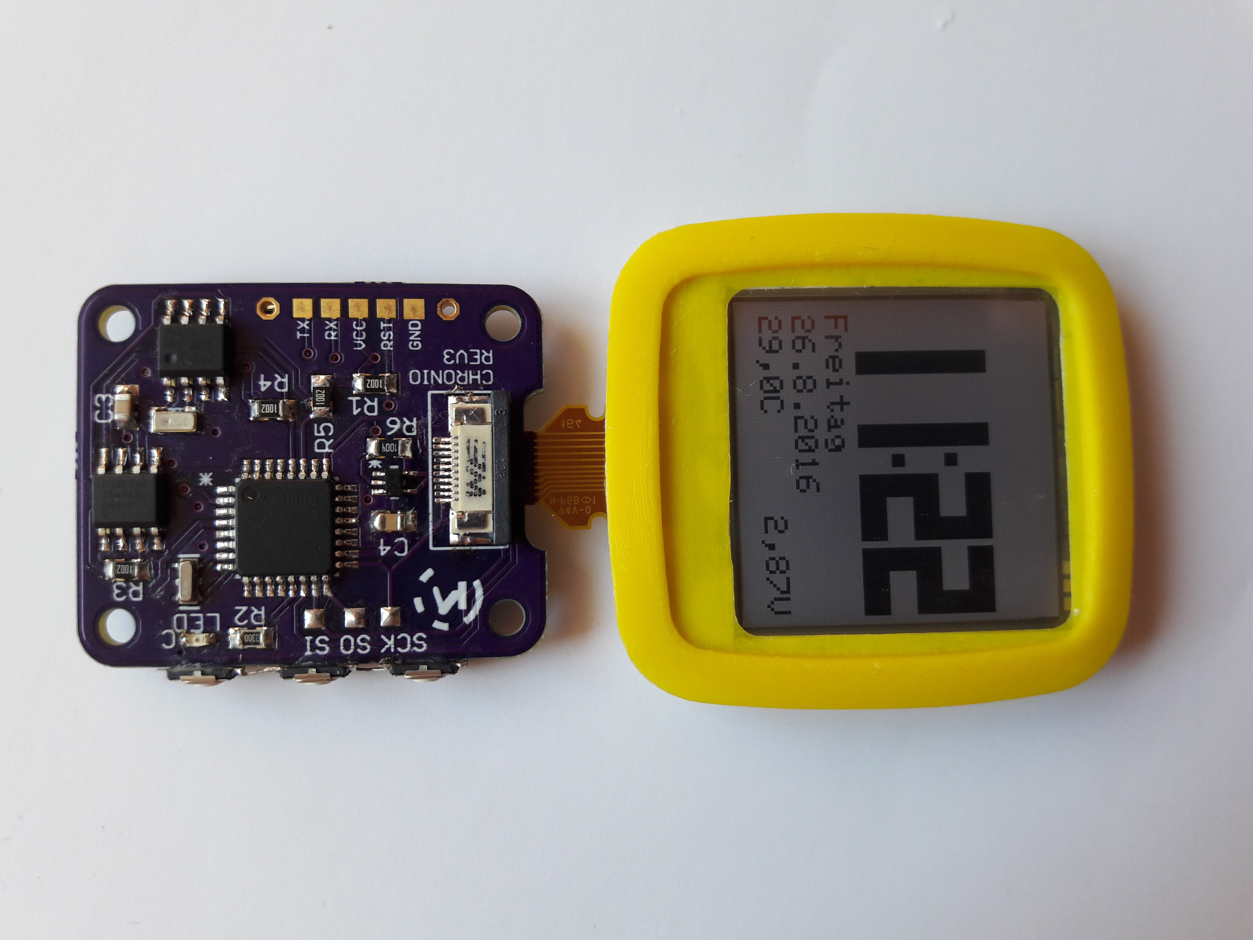
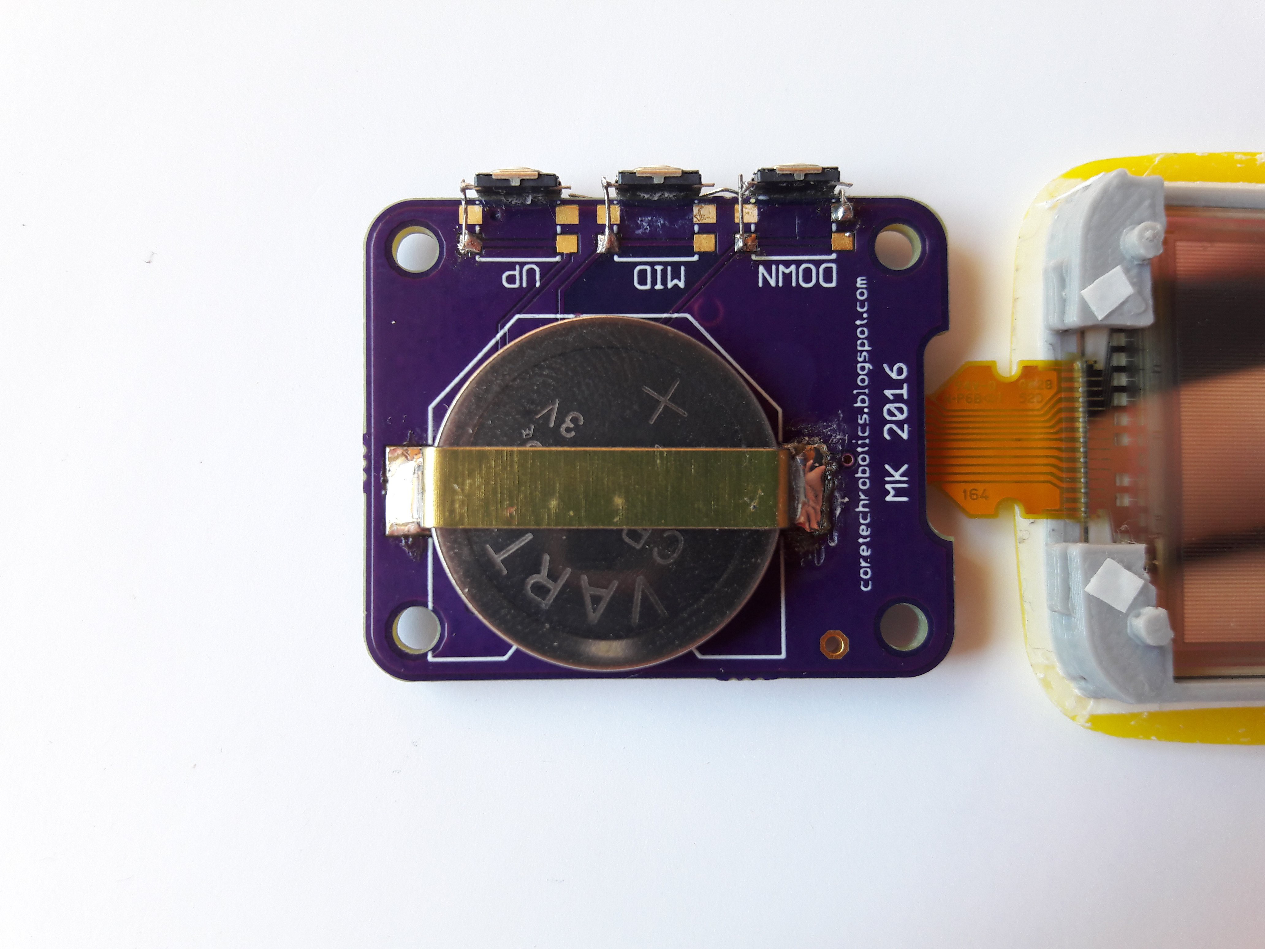 As you can see from the pictures, I chose side-mounted buttons instead of the SMD ones. The big buttons just have better feedback when pressing them. Also I soldered in a piece of a folder as a battery holder again. Sadly I used a slightly smaller battery for aligning the part. When I slid a new one in, I used too much force and liftet a trace off the PCB. It was fixed with glue but doesn't look that great now.
The watch is currently sitting on a shelf where it has been running with a CR2025 for almost 6 weeks now. The displayed voltage is still at 2.87 V. After reaching a month of battery life I considered the project a success. But it would not have worked without going through all the trouble of fixing the VCOM signal.
There is one other solution to the 1 Hz signal problem: The TS300 series from Silicon Labs (http://www.silabs.com/Support Documents/TechnicalDocs/TS3005.pdf) can generate a 1 Hz square wave at just over 1 uA. Unfortunately the part is only available in a DFN package, which I can't solder by hand. At least not properly. But for an improved, more compact version of the watch, this would be the way to do it.
Discussions
Become a Hackaday.io Member
Create an account to leave a comment. Already have an account? Log In.
The TS300 is good solution for 1Hz generation, but that IC is at end of life. Take a look at SIT1534AI-H4-DCC-00.001E (or ASTMK-0.001KHZ-LQ-DCC-H-T)... they can be soldered as easy as SMD crystal. I'm playing with LS027B7DH01A (similar to display in Chronio, but a little bigger). Currently the 1Hz meander for the display is generated by the low-power timer in microcontrollers (LPTIM in STM32L4), but I want to get rid of dependency on the CPU, so I've tried to find something low-power to generate a 1Hz signal. Found your blog and mentions about TS300... soldering its DFN case is not problem for me, but this IC is in NRND state... sad... but I've found Sit1534 (or its full analog ASTMK). This IC looks great.
And your project is awesome, now I know how my LS013B7DH06 displays will be used :)
Are you sure? yes | no
Hi !
Thank you very much for all this documentation of your project !
I'm using the bigger version of the sharp LCD, LS044Q7DH01. For the same reason of you, I search to maximise the sleep time of the micro. I don't know if this version is less sensible to burn-in, but with a COM inversion period of 2 min (120 seconds), I did not yet observe any screen burn-in (around 2 month of continuous running).
Do you have picture of the burn-in phenomenon ?
Thanks again and congratulation for this nice watch !
Are you sure? yes | no
You're welcome. Unfortunately I don't have any pictures of the burn-in and I am doing a battery life test that I don't want to disturb. The burn-in mostly occurred on the big digits on the watchface. It looks like a 7-segment display with a faint 8 behind the current digit. Over time it gets more and more difficult to read text and numbers. There must be a difference between the smaller and bigger displays. I got massive burn-in on the watch after only a day with a 60 second period. Two minutes is a lot, that means you can just wake the micro up with out any signal generators.
I just found your wireless LCD project, great job! I really need to build a project with an ESP8266 now.
Are you sure? yes | no
You can change the alarm to 1 sec and drive both the LCD and AVR. The AVR just have to use a software counter to do the update once every 60 wakeups. It is like 5 lines of code.
Alarm -> hit snooze... 59 times -> finally wake up to update display and then go back to sleep.
Are you sure? yes | no
That would have been the easiest solution. But from what I measured the Atmega takes about 100ms for waking up, toggling a pin and going back to sleep. That would be too expensive if I had to do it once per second.
But the startup time seems to depend mostly on the oscillator, so this may be something I have to look into. There is a thread on the Arduino forums about this topic: http://forum.arduino.cc/index.php?topic=142821.0
Are you sure? yes | no
Run the AVR off internal 8MHz RC. According to Table 9-12. Start-up times for the internal RC Oscillator clock should take 6 CK.
Are you sure? yes | no
Thank you for the information. I am going to test this and see if it works.
Are you sure? yes | no
I'd look into the MCU option like Jaromir suggests; I bet it can be done with very low power consumption. But, without knowing anything else about it, if you really do end up needing an auxiliary circuit to generate 1Hz pulses at ultra-low power consumption, the TPL5010 from Ti can do it at 35nA (!) in a hand-solderable SOT23-6 case:
http://www.ti.com/product/TPL5010
Are you sure? yes | no
[this comment has been deleted]
Oh, yeah, my mistake, the TPL5010 can't do it, but I thought the DRV signal out of the TPL5110 (or TPL5111) was at a 50% duty cycle. Looking more closely, the high time is always 50ms short of a square wave - it approximates a square for long delays.
You could always divide a faster clock (like a 500ms timeout pulse from the TPL5110) by two with a 74AUP1G80 flip-flop (0.5uA max) to ensure 50% duty cycle (modulo clock jitter):
https://www.digikey.com/product-detail/en/texas-instruments/SN74AUP1G80DCKR/296-19084-1-ND/864315
It's available in an SC70-5 package, which may be hand-solderable depending on your hands. I can do one with a little care.
That brings you to 0.55 uA max for both.
Are you sure? yes | no
You are right, the TPL5110/TPL5111 seems to be capable of generating the pulse. I have been searching the internet for a solution but somehow overlooked this. There is an excellent writeup on the TPL5111 and this problem here: http://forum.43oh.com/topic/4979-sharp-memory-display-booster-pack/page-5#entry69790
They are talking about 40 - 400 nA for toggling the signal.
Now I feel dumb. I need to get my hands on one of those chips. :)
Are you sure? yes | no
Thanks for the suggestion. The low power consumption of the TPL5000 is great but I couldn't find a way to get more than a short pulse out of it. The display requires a 50% duty cycle which makes this more complicated.
Are you sure? yes | no
Did you actually try to generate 1Hz toggle signal directly from IO pin of MCU? What is the current consumption in this mode?
The MCU can enter sleep mode after the toggle action (which is itself perhaps a few dozens of instructions altogether), so it is going to sleep for most of the one second (or what will be the toggling frequency) time frame.
Are you sure? yes | no
I measured that the whole process takes about 100ms. And the Atmega draws more than 3 mA during that. That wouls mean an average current of 300 uA. But there may be a way to lower that by selecting the internal oscillator. Also it is difficult to get a precise time without an oscilloscope.
Are you sure? yes | no
Oh, I see. I totally thought you are using ARM MCU, just like in Arduino zero - and now I learned you have Atmega328p, sorry for confusion.
The 100ms is startup time of oscillator. You can partially change it by selecting CKSEL and SUT bits in fuses - see page 30 in datasheet
http://www.atmel.com/Images/Atmel-8271-8-bit-AVR-Microcontroller-ATmega48A-48PA-88A-88PA-168A-168PA-328-328P_datasheet_Complete.pdf
The AVR is really showing its age with its unflexible clock circuit. Running into XTAL oscillator after waking up from sleep is not exactly ideal solution and it seems like AVR can't do much better - so, under those circumstances using external clock source could be really better solution.
Are you sure? yes | no
The ATmega328 is not really a good choice for a project like this. But I wanted to make it Arduino-compatible so more people have a chance to experiment with it. Most Microchip MCUs have more flexible oscillator settings and the EFM32 even has a low power timer that can be used to toggle the VCOM signal while the device is sleeping.
Would you say that a ARM MCU like in the Arduino Zero would have a faster startup time? I have not yet worked with these chips and always thought they have an even higher power consumption than AVRs.
Are you sure? yes | no
If the MCU has option to switch to internal oscillator before entering sleep mode, it will be much faster to wake up. External XTAL is perhaps the slowest possible oscillator for startup.
You may consider using Atmega328 at internal oscillator. It is so-so usable with arduino, though high tolerance of internal RC oscillator (another weak part of AVR) may cause the serial bootloader to fail. The internet is full of "it works for me" success stories, but one should keep head calm and stick to datasheet numbers.
The current consumption may be actually lower, as the ARM core is more powerful than AVR, so you can do the task quickly and enter sleep mode. Peripherals are more advanced, so you can do some things without CPU intervention. As I quickly skimmed the datasheet, it looks like the SAMD has higher sleep current (2,8uA, really?), on the other hand.
I have done my low-power applications with Microchip MCU, where you can switch oscillator modes as you wish and enter sleep mode with less than microamp current draw.
You may want to disregard the arduino altogether. It is nice platform for a lot of things, but sometimes not. Right now it is causing you more troubles than helping you.
Are you sure? yes | no
I also worked with Microchip MCUs before and switching to a different oscillator is basically one line of code. On the ATmega328 you have to burn the fuses with a programmer. I already tried the internal 8 MHz oscillator but it's not that reliable and I didn't do a test on how long it takes to wake up. Still I like the Arduino environment and rewriting the libraries for a PIC was too much work for me.
Are you sure? yes | no