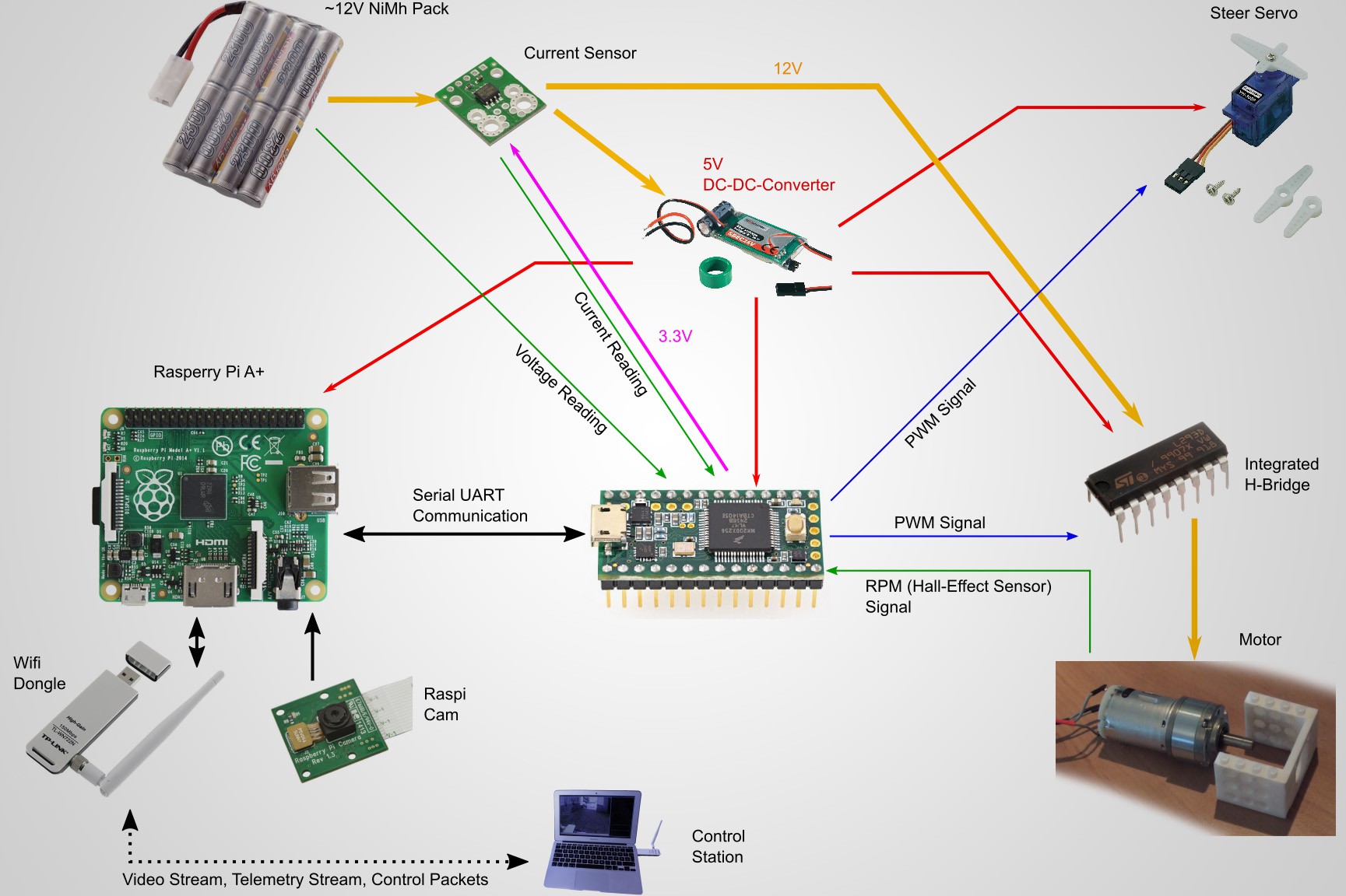
Sketch of the electronics
Its heart is a Teensy 3.2 microcontroller board. It is fast, has plenty of peripherals and is easy to use due to Arduino compatible libraries.
I use an H-bridge IC, the L293, as motor driver, allowing to drive in reverse. It is rated for 1 A. The LEGO motor draws less than that. The motor that I bought after that is still in the 1 A range. So no worries.
I measure the battery voltage straight forwardly in the middle of a voltage divider. This drops the voltage proportionally to something that can be safely connected to the input pins of the uC. I added a OpAmp buffer, because it avoids loading effects and I had one free unit of my dual OpAmp.
This configuration uses a ACS 711 hall effect current sensor on top of carrier board. I found it helpful to filter its output and amplify it with an OpAmp. It is a bit noisy, however tolerable.
The circuit can be powered by 9 - 12 V from the battery or the PSU. My version of reverse polarity protection is made of a diode and a polyfuse. In case I connect power in reverse it becomes the problem of the power supply to handle the current for a brief period.
The uC board, RaspberryPi's and servo motors need a supply of 5 to 6 V. So I ordered a common switch mode regulator for RC models from Conrad. It is rated for 5 A which is plenty for the little servo and the electronics.
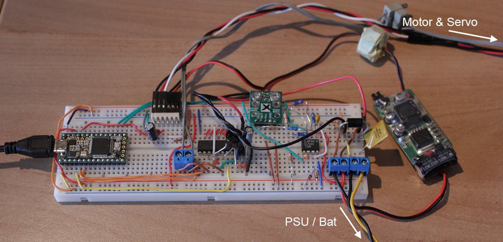
I put (almost) everything on a breadboard. Has to be good enough.
Basic WiFi Link (ESP8266)
To get started, I ordered a small WiFi-enabled SoC board, the Olimex ESP8266 Dev board http://www.exp-tech.de/olimex-mod-wifi-esp8266-dev. Thanks to other cool dudes there is an Arduino compatibility layer https://github.com/esp8266/Arduino, which makes programming the chip very easy. Note that the board has no voltage regulator of its own. However, it can be supplied with the required 3.3 V by the regulator on the Teensy board.
Base station, ESP8266 and the uC communicate via a simple packet based protocol.
I didn't bother with anything fancy, but encode just numbers in ASCII Hex format. Thus a packet has the form "@x1;x2;x3;...$", where "@" and "$" delineate start and end of the packet. The integers x1, x2, x3 are the payload. The advantage of this protocol is that the data is still somewhat human readable.
The program on the ESP8266 relays packets bidirectionally over WiFi as UDP datagrams. It does nothing else. The packets arrive intact if they arrive, so no error correction on my side is required. The communication with the Teensy board goes through the UART serial interface.
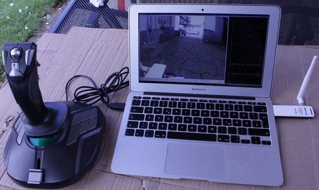
Maximum range, outdoors within line of sight is approximately 70 m with the ESP 8266 configured as access point and a Mac Book Air as remote control. I mounted the WiFi-adapter on a little pole to keep it away from interference. It also looks cool.
Later on where I used the Raspberry Pi, it does the packet relaying in principle in the same manner. In addition, the RPi has to deal with video of course.
Raspberry Pi & Wifibroadcast
Wifibroadcast (WBC) https://befinitiv.wordpress.com/ is a project that allows data transmission over wifi without device association, much link an analog link. It's core comprises a rx and tx programs.
It eliminates the case of failure where devices fail to reconnect after a temporary disruption, e.g. due to blocked line of sight. It also allows for damaged packets to arrive - useful for video transmission.
Following the author of WBC I obtained a Raspberry Pi A+ and a camera module for it https://www.raspberrypi.org/products/camera-module
. Getting the Pi to capture a video stream is straight forward with raspivid. Video compression is already already performed by raspivid, which is nice, albeit the format seemed fixed to h264 at the time.
I open three logical transmission channels on the Raspberry Pi. One for telemetry, one for commands and one for the video stream. Each channels is managed by an instance of the tx or rx program of WBC, respectively. Usually WBC is used only for video. And indeed the RPi A+ can barely handle 720p video with my additional load. It frequently locked up for a second or so. This has not yet occurred with the Raspberry Pi 3 that I use now.
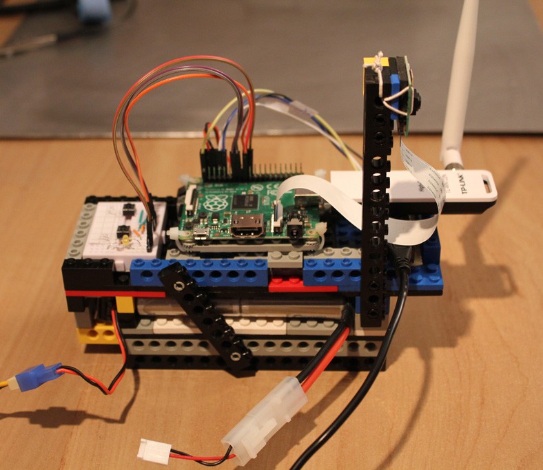
Above, the testing rig. Video-only in 720p easily possible over 100 m distance to my Mac Book. I haven't checked the maximum range yet. Time lag is about 300 ms. Not exactly great but also not catastrophic. Lag is subjectively lower with the RPi 3. Didn't measure.
The WiFi Stick is the TP-LINK TL-WN722N as per recommendations for WBC. There is one on the vehicle and on the control station. It has given me zero trouble so far.
Remote Control Station
It is really just my trusty old laptop! It runs a dual boot setup with Linux and Mac OS. Very handy.
The software it is written in Python using PyQt for the GUI, PyQtGraph for graph plotting, PyGame for input handling.
After evaluating various means of video streaming, I decided to use Libav https://libav.org/ directly and coded a little ad-hoc decoder module. Very useful code samples: http://roxlu.com/2014/039/decoding-h264-and-yuv420p-playback, http://dranger.com/ffmpeg/ffmpeg.html.
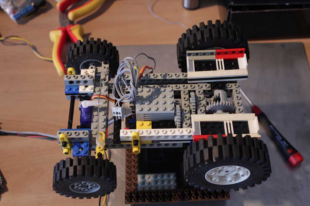
Chassis & Motor
Making good use of LEGO. The first version used an old LEGO motor. Is rated for 9 V and runs at high RPM and low torque. Therefore a gear box is required. I needed a differential gear to drive through curves. A cool guy compiled a nice overview of different LEGO motors there: http://www.philohome.com/motors/motorcomp.htm.
The steering mechanism is made from a cheap mini servo and a steel rod from a CPU fan mount. Works quite well actually.
3D Printed Parts
Made from Polyamid by laser sintering. Both the camera as well as the larger (non-LEGO) motor needed to be mounted somehow. 3D printing appeared like a suitable solution. The parts were designed by me and manufactured by https://www.trinckle.com.
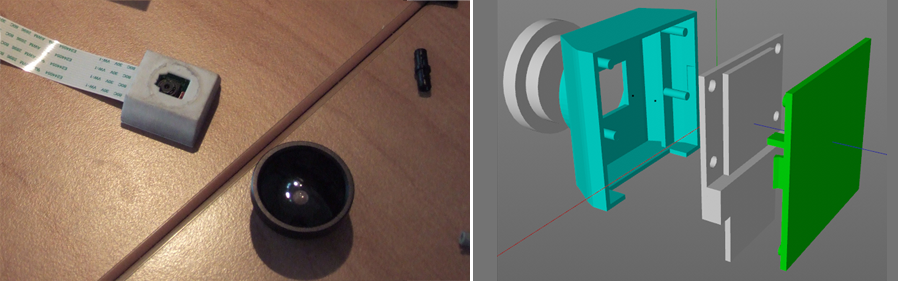 Obviously the the housing of the camera has the cutout in the wrong place. DOH!
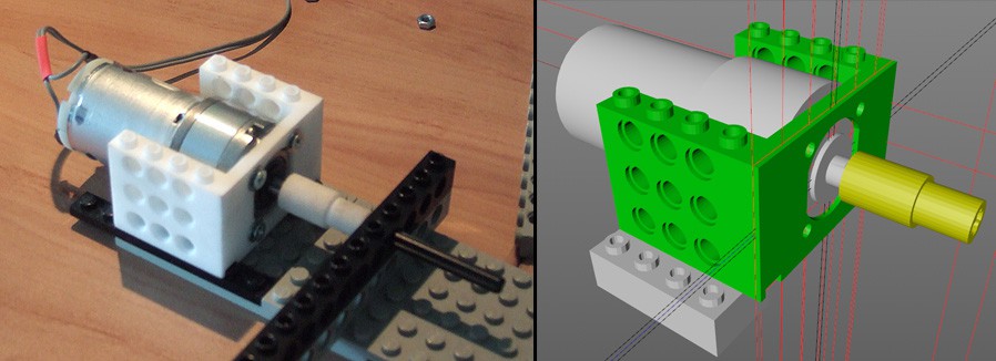
Speed Control (1st Attempt)
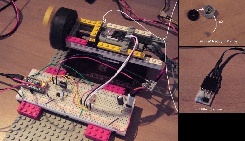
What I conceived involves Neodym magnets mounted to the engine shaft and a pair of hall effect sensors http://sensing.honeywell.com/honeywell-sensing-ss400-series-product-sheet-009050-3-en.pdf to detect the passing of the magnetic fields. By the order of activation of both sensors it is relatively straight forward to not only measure the frequency but also to figure out the direction of rotation.
Left: Step response of measured frequency vs time. PWM value of 255 corresponds to 100 % duty cycle. Right: Frequency vs PWM after reaching steady state.
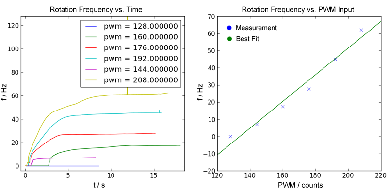
The control algorithm is more or less a standard P-I-controller https://en.wikipedia.org/wiki/PID_controller.Parameters were guesstimated from the step responses of the motor.
Back EMF Sensing
With the new motor, that is used on the second version of the vehicle I decided to attempt to measure the motor speed by sensing the back electromotive force (EMF). Beside curiosity this had the practical reason that I found no place to attach the magnets.
Back EMF is the voltage induced across the motor terminals by the coils turning in the magnetic field of the permanent magnets in the motor. It is proportional to speed and can be measured directly when the motor terminals are floating and the current through the coils completely decayed.
There are some nice articles on the net which I followed. https://sites.google.com/site/hobbydebraj/home/dc-motor-control-using-back-emf-sen, https://www.precisionmicrodrives.com/application-notes/ab-021-measuring-rpm-from-back-emf, https://acroname.com/articles/back-emf-motion-feedback.
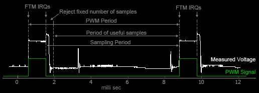
Drawback of this method is that I cannot run the motor at 100% duty cycle because there needs to be some interval during which to take voltage samples. Moreover, the current needs time to decay. This puts an upper bound on the PWM frequency.
Plot of the voltage waveform:
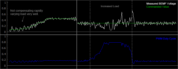
Plot of quantities while using the BEMF voltage for speed control.