 agp.cooper
Electrical Interference
I have made a serious error in this project trying to use a common power supply for the steppers and the other electronics.
A serious error that has cost weeks if not months of extra work!
Twisted pairs for the cables and decoupling capacitors on the stepper motor outputs seemed to fix the problems.
The problems appear to be two fold:
- Inductive currents coupled to signal lines.
- Inductive voltages on the power supply lines.
Inductive currents coupled to the signal lines
These upset the signal lines (i.e. inputs to the MPU) but I doubt they have enough power to destroy a device (i.e. eight HC-SR04).
Twisted pairs on the power/stepper/signal cables works wonders here.
The HC-SR04 has a 10k pull-up resistor on the trigger (input) and echo (output) which obviously helps (reduces sensitivity to inductive currents).
Reducing inductive currents
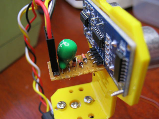
Previously, I added 100nF decoupling capacitors across the stepper motor terminals which reduced noise and very likely electrical noise (from the PWM).
My back of the envelope calculation was that the resonance frequency was 2.6 kHz.
Which is well above the operating speed (<=400Hz) and well below the PWM frequency (>>20kHz).
I found an application note for the designed of LC low pass filters for stepper motors.
Worth a review if it reduces the EMI further.
I don't think I am having any problems with inductive coupling any more but before the next set of tests I will run the steppers by themselves and check all the drive board power and signal lines.
Ran the tests, I only found some ripple on the battery line, everything else was clear.
Inductive voltages on the power supply lines
At last count I have "buried" eight HC-SR04s.
Probably killed the MAX232 as it a 5v device (6v absolute max).
Certainly the servo killed the last two as they shared the same power supply (note the 13v inductive kick-back - limited by the 5v regulator diode back to the battery):
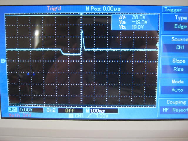
The inductive pulse is pretty high powered, at least 2 Ampere as the power supply (5v) has been pulled down to less than 3v (in the above inage).
The servo now has its own high current power supply and a 100uF capacitor to absorb the inductive spike (now less than 8v).
Reducing the output voltage to about 4.9 volts and adding a 5.1v 1W zener to the voltage regulator output reduces the inductive spike to "ripple".
Software Problems
Had some problems with servo sweep stuttering due to background processes interrupting the timer.
Here is a bad version where I try to lock the frequency:
#define servoPin D4
const int minAngle=15;
const int maxAngle=175;
int servoDir=5;
volatile int servoState=0;
volatile int servoAngle=90;
volatile unsigned long next;
void inline servoISR(void)
{
  if (servoState==0) {
    digitalWrite(servoPin,HIGH);
    servoState=1;
    next=next+40000+889*servoAngle;
  } else {
    digitalWrite(servoPin,LOW);
    servoState=0;
    next=next+1560000-889*servoAngle;
  }
  timer0_write(next);
}
Here is the fixed version where I let the frequency slip:
// Servo defines
#define servoPin D4
#define minAngle 15
#define maxAngle 175
volatile int servoDir=5;
volatile int servoAngle=95;
volatile unsigned long next;
volatile int servoState=0;
void inline servoISR(void) {
  next=ESP.getCycleCount()-180;
  if (servoState==0) {
    digitalWrite(servoPin,HIGH);
    servoState=1;
    next=next+40000+889*servoAngle;
  } else {
    digitalWrite(servoPin,LOW);
    servoState=0;
    next=next+1560000-889*servoAngle;
  }
  timer0_write(next);
}
It is not a perfect fix but the stuttering is gone.
The second issue was requirement to yield to background processes.
Any loop that is more than 50 ms must yield.
The yield() instruction can be replaced with a delay().
The optimum delay appears to be 2 ms (i.e. delay(2)) based on comments by other people.
HC-SR04 Time Out
The HC-SR04 datasheet states that the HC-SR04 time out is about 38 ms.But I am finding that after 40 ms the echo has not come (i.e. timed out).
Currently the software fires the next trigger pulse that triggers an echo about 300 us later (not good) but this is not consistent between sensors.
Increasing the timeout to 80 ms does not help.
Slowing the repetition rate down to 250 ms showed the HC-SR04 timing-out of about 185 ms (for two different HC-SR04s) to 200 ms (for another two different HC-SR04s).
So if I want to detect a timeout I will have to wait about 250 ms.
I checked and confirmed this long time out using Nano and the real pulseIn().
I have updated the code and it now works as expected (except for the 185 ms time out period).
Bug
Something I noticed was that I could not write out (Serial.println()) the value of pulseIn (which is a global volatile variable) inside the readSensors() procedure but it was okay in loop(). Procedure readSensors() is called by Ticker. Strange!
Next
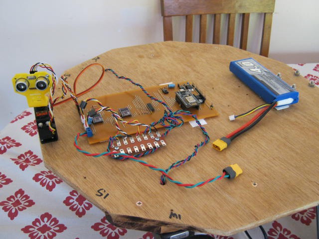
Next is to use the sensor return values to drive the stepper motors.
Here is the new setup:
AlanX
Discussions
Become a Hackaday.io Member
Create an account to leave a comment. Already have an account? Log In.