Close
0%
0%

A Home Automation System

I hacked my own LED lighting control system into a home automation system.

Similar projects worth following
I extended the QualColor color-wash LED control technology that I designed many years ago to support some home automation tasks such as temperature and control of relay-based devices and traditional white lighting. It uses a distributed architecture that communicates via a proprietary wireless protocol running on top of nrf24L01+ and nrf24LE1 radios (as well as a direct wired communication channel). Currently it controls custom LED fixtures and traditional light fixtures, the furnace and several decorative LED sculptures throughout the house. The system is operated by custom wall-mounted controls, wireless remote controls and a web-based interface with displays optimized for phones, tablets and computer web-browsers. I plan to continue to extend it with additional devices under control, new wall controls and additional functionality for energy monitoring and security.

I am interested to see if any of the technology described by this project is of interest to others.

A bit of history. The original QualColor LED lighting system was comprised of a touchpad-based RF remote control and three receiver/controller/drivers as well as a custom RGBW light fixture. QualColor is a distributed architecture with the local controller responsible for things like fading between colors and mapping color to output channels (e.g. RGB, RGBA or RGBW). Colors are described using the HSV color space. Unlike LED systems like the ubiquitous WS2812 LED strips that take a constant stream of data from a central controller, the QualColor system uses packetized commands to set colors or initiate a fade (interpolated) to a new color over a period of time. Communication is bi-directional and broadcast. Packets include addressing information that allow specific controllers to choose to execute them. The distributed architecture allows multiple control devices (e.g. handheld control, computer, etc) to send commands to any controller. State is managed by the controllers and may be queried by a control device if it requires it. Addresses consist of a 16-bit Zone and either 16-bit Unit or 8-bit Group (called Unit or Group addressing). Unit addressing allows commands to be sent to a specific device. Group addressing allows commands to be sent to multiple devices that are part of a group. The addressing supports wildcard addresses so a command can be sent to all units in a Zone for example (e.g. all lights in the kitchen). The RF protocol is a simple broadcast protocol with some built-in synchronization for multiple transmitters using the Nordic nRF24L01+ radio at 250 kbit/sec (for maximum receiver sensitivity) with the ability to add a repeater. The original design goal was for a remote control to operate fixtures in the same room and the Nordic radios were quite adequate for that.

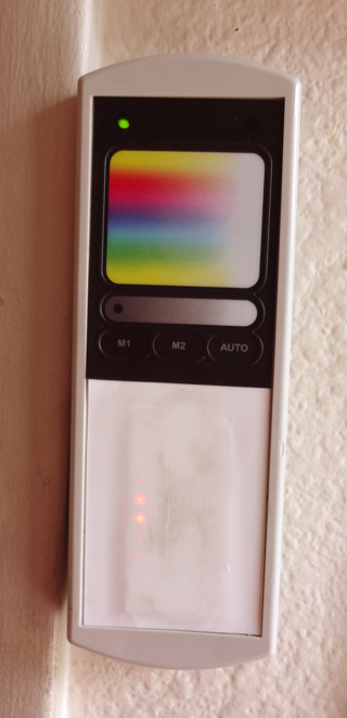
The remote control utilized a touchpad with a color-picker graphic overlay and support for memory presets and initiating an automatic program (for example slowly changing random colors). It also had a USB interface to allow configuration and system control via a computer (the remote acting as a wireless interface into the system).

The original three systems were:
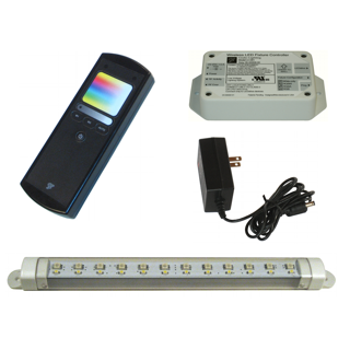
QualColor "Ambi" - Controlled up to 10 custom RGBW fixtures connected with standard Cat5 cabling.
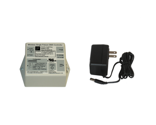
QualColor DMX - Controlled a multi-channel LED DMX fixture (White, RGB, RGBA or RGBW).
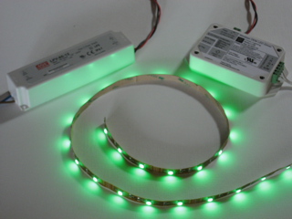

QualColor OEM - Controlled 12- or 24-VDC LED strips (white, RGB, RGBA or RGBW).

There was also some PC/Mac based software for configuring these systems or allowing computer control. As part of the development of the system I also designed a USB-based RF interface/repeater but it wasn't productized.

I sold the systems directly and ended up having limited success because, in traditional techie style, underestimated the sales effort. However I was left with a bunch of technology that could find other uses...

  • A note about security and future plans

    Dan Julio08/24/2016 at 04:44 0 comments

    A note about security

    Although security was not at the forefront, as it is today, when I started designing the QualColor RF protocol in 2007 I made some small effort. I had read a comment online that said unless you were an expert in cryptography and computer security then you shouldn't try to implement something so I decided that my effort would be to secure a system from casual hackers (e.g. be able to prevent someone with one of my remote controls from controlling a system that had been secured) but not from experienced hackers (who, today, would be able to sniff the system using a SDR). The wireless variant of the protocol includes both a 8-bit Network code that modifies the Nordic Radio addresses and a 32-bit key that must match for packets to be validated. These are communicated between a control device and the device being configured by a special SetAddrRf packet that should only be transmitted during a provisioning step when the system is installed. Of course this packet could also be snooped by a sophisticated hacker. The RF modules initially had a provision to reduce the output power of the radio to a minimum value with the idea to make it harder to "listen in" to the provisioning activity but I never implemented control software to take advantage of this feature. Initially configuration and parameter values in any device could be changed by packets addressed to the device but I eventually changed the system to require that the link button be pressed before any changes could be made to a device to at least require a physical interaction with the device. This makes it difficult, however, for someone to modify a device's configuration when it is installed in a physically inaccessible location or to change devices remotely.

    The wired protocol has no specific security capability other than the need to press the "link" button to make any changes to a device. I debated adding a key but ultimately decided that if someone gained physical access to a network then they would have the capability to snoop the key.

    Some of the implementations of my system that interface with TCP/IP networks include more sophisticated security up to the Electric Imp controller that used HTTPS. The home control program requires any user accessing its web interface from an IP address outside the local address (e.g. 10.X.X.X) enter a user id and password. The control program at Solid State Depot requires this for web access (which means users from the local network just immediately get a virtual control panel but we can also control the lights remotely. However it also exposes a simplified packet interface for hacking with absolutely no security on the local network (depending on our firewall to prevent remote access).

    One of the things I think about in releasing my system as either hardware modules or as open source is the level of security. I think that re-implementing the architecture on more modern micro-controllers and with higher-performance radios than the Nordic devices might allow for a much higher level of security. But perhaps, considering the advice I read so long ago, that ultimately isn't that important as long as the external interfaces are protected.

    My plans
    My current plans for my own system include the following

    • Finish the environmental sensor and replace the stand-alone temperature sensors (move them to the makerspace)
    • Modify the control software to include predictive control of both the HVAC and lighting system based on sensor data
    • Add a scene control module that includes both preset scenes and randomly generated lighting effects as well as the ability to trigger scenes based on environmental control (for example lighting based on the external light levels)
    • Write an authoring program to create the configuration files including system topology, predictive control rules and scene descriptions
    • Include some additional sensor data including power monitoring and video feeds into the control program
    • Include the ability to record environmental/video/security...
    Read more »

  • QualColor at my Makerspace

    Dan Julio08/20/2016 at 05:01 0 comments

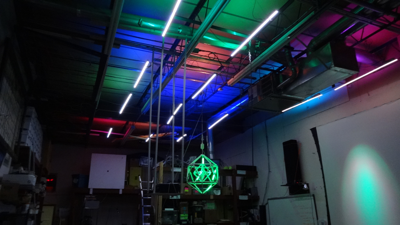
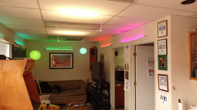
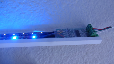
    The main bay at my makerspace, Solid State Depot, in Boulder was lit by a set of fluorescent fixtures that were slowly failing. There was talk about replacing the bulbs with drop-in LED replacements but a "friend" offered me with the statement "We'll give him only enough money to make him feel obligated to complete the job". In reality the project became a group effort and we used a bunch of white and RGB strips controlled by a simple custom driver using a Link Series controller. White light was generated by a combination of warm and natural color temperature LEDs with RGBW uplights. The lobby and main bay are 100% LED lit. The main bay white lighting is also coupled with sound effects that can play when it is turned on or off.

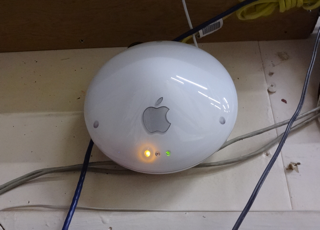
    I built three customized control devices for the space. A combination color and linear touch sensors to control the main white and color fixtures in the lobby. A custom device that used an arduino, sound effects shield and the guts of a touch remote to control lighting in the main bay and an Apple Airport enclosure gutted and fitted with a Raspberry Pi 3 and QualColor USB interface to provide a web interface as well as a TCP/IP port for direct access to the system for anybody to hack with.

  • The current QualColor system

    Dan Julio08/19/2016 at 18:58 0 comments

    Over the years I designed additional prototype controllers and drivers. As I mentioned earlier, the QualColor protocol is packet and command based (for example, as opposed to streams of intensity values used by WS2812 LEDs). Packets are small, 16 bytes or less and grouped by function type. There are provisioning packets that all devices interpret like SetAddress or SetRfAddress. Device-specific configuration packets (for example packets to set configuration or calibration data that are device dependent). Light commands such as SetHSVcolor that sets a color value immediately or FadeHSVcolor that fades to a new color value over a specified period of time. Information and Error report packets (for example an over-temperature Fault condition reported by a light controller). HVAC commands to read temperature values and configure set-points. One of the primary architecture goals was to make a distributed system so that any one control device wouldn't have to know anything about the devices it was controlling. The original handheld touch color remote control can control one or a million fixtures. It can also control a fixture with a controller designed long after it. One requirement of the protocol is that packets are visible to all devices. This puts an upper limit on the number of changes that can occur at a time but I tried to design a reasonable goal for a lighting and home control architecture. The wireless links can support (with repeated packets) about 100 packets/sec. The wired links can support a higher rate.

    I chose the HSV color space because it allowed me to separate color specification from implementation. Over time I have supported dimmable white, dimmable and non-dimmable white, RGB, RGBA and RGBW implementations. Each controller is responsible for mapping HSV to its specific implementation. HSV also allows neat tricks like fading to a color 180 degrees around the color circle from the current color which is useful when making didactic or tridactic color patterns with multiple fixtures without having to know what the current color is (for example it has been randomly chosen at some previous point). The HSV control packets also include a set of flags that allow control devices to only change some of the HSV components, or to apply them as a delta to the current values (the button remote in the kitchen uses this function so that each press of a set of buttons increases or decreases the current intensity of one fixture by a few percent).

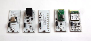
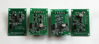
    Because I had controllers that worked both wirelessly and via the wired connection, I separated control functionality from driver functionality on a set of boards sized to fit in single-gang switch enclosures. For example either the wired or wireless controller board can connect to one of 4 different LED driver boards via an 8-pin flat cable.

    Front Boards (left to right): nrf24LE1 wireless LED controller, Wired LED controller, Touch Control with two different firmware for touch dimming or scene control, wired to wireless interface, Electric Imp interface board for IOT functionality. Each of the LED controllers has the same functionality and can be configured to control white-only, RGB or RGBW fixtures. The Touch Control has a linear slider but I created another piece of firmware that splits it into four "buttons", each of which can send commands, for example for scene control. The wired to wireless interface bridges the two, can interface via a USB board to a PC, can act as a repeater or interfaces to a special set of LED controllers called Link Series devices. The IOT board was an experiment in remote access via Electric Imp's cloud system. It basically extended the QualColor protocol via the Imp's HTTP protocol. It worked with some latency but I never completed a process of automatically enrolling Imps with an app.


    LED Driver Back Boards (left to right): Single channel (white) switch-mode constant current driver, 4-channel constant voltage driver (e.g. for RGB or RGBW strips), 4-channel constant... Read more »

  • Decorative Lighting

    Dan Julio08/18/2016 at 04:53 0 comments

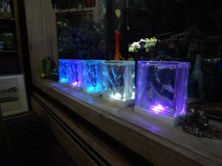
    The great thing about a log home is that the wood is very friendly to light. It is easy to make a warm and inviting atmosphere using lighting. I have been surrounded by artists my entire life and although I am no artist I have an appreciation for the importance of art in life. With lighting I have tried to add my small part. And, of course, it should all be part of the home automation system. This post just contains photos of the fun parts of the lighting system.

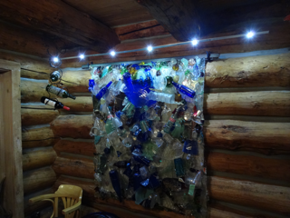
    One of two glass block sets lit with a single 5050 RGB LED on a smart "pixel" controller board mounted in a milled plastic base.

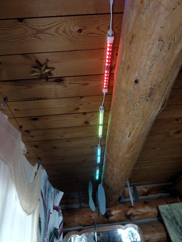
    "Light Bar" above a glass sculpture. Six dimmable 1-Watt HB LEDs on an aluminum bar suspended from the ceiling.

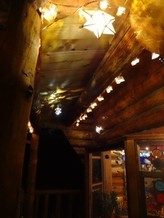
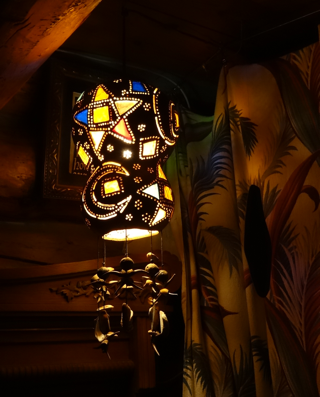
    Deck Lighting with collected Mexican light fixtures full of LEDs controlled by a dimmer and strings of traditional incandescent lights controlled by a relay controller.

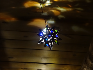
    Collected Mexican Star lamps filled with dimmable LEDs.


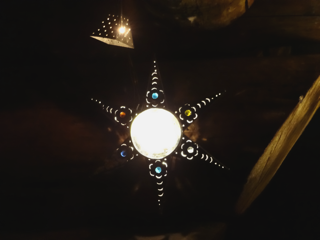
    Mexican Jellyfish lamp controlled by a relay controller.

    Eight color wash fixtures lighting the curtains in our bedroom.

  • Central Control

    Dan Julio08/17/2016 at 23:23 0 comments

    Our usual ways of interacting with the system are through the physical controls, either mounted on the walls or remote controls here and there. However I wanted to provide remote access and have a place to put some automated intelligence over time. I looked at a lot of the open source home automation projects and marveled at how comprehensive they are. Ultimately though I decided to roll my own. I wanted to design my own user interface. I didn't really like any of the other ones I saw and I knew my artist partner wouldn't. And I had a lot of existing library code to interface with the QualColor protocol.

    I use a development environment called xojo (formerly Real Studio). It lets me spit out applications for Windows, OS X and Linux as well as IOS for iPhone/iPad and stand-alone web server applications without having to learn a lot of other software stacks. I am definitely one of those people who wants the end result over finding the most perfect way to get there.

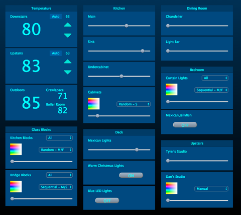
    The control program is currently very simple. It runs on an old Mac laptop (eventually will run on a Pi 3). It is configured using a simple XML file and interfaces to the rest of the home via one of the prototype USB interfaces with a repeater to get coverage of the entire house. It provides a web interface with a login for any addresses that come from a different net. It's pretty straight forward object oriented code with functional and display objects for each kind of device. xojo lets me create different web views depending on the size of the device's screen and I take advantage of this feature for desktop browsers, tablets and phones.

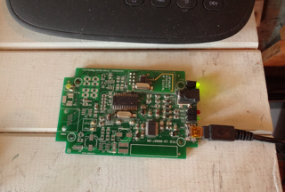
    USB interface on "equipment" shelf...

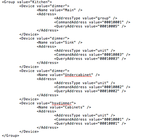
    Example XML configuration.

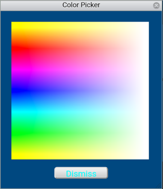
    Color wash light fixtures get additional visible controls to display a color-picker for manual color selection as well as a pull-down menu to select one of their built-in color wash programs (either random color fades or a rainbow cycle, each at one of four speeds). You can see how this is specified in the XML. A white-only dimmable fixture has a Device Value of "dimmer". A color-wash capable fixture has a Device value of "hsvdimmer". Currently the color picker only detects initial touch down and not dragging. I'd like to modify it to generate a continuous set of values as people drag their finger or mouse across it so that it operates the same way the physical remote control does.

    Groups of fixtures, for example that are in some sculptural pieces are condensed into a single control but with an additional pull-down menu allowing address selection (all units, specific sets of units within the group or individual units). By default the user interface tries to display the most general and commonly used selections.

    The control program takes advantage of a feature of the touch dimmers with LED indicators. They are designed so that they can either directly query the device they control for its current value to update their LED display if some other device changed its value or they can watch for query packets to their device to go by and update the value based on the response to those queries. Every few seconds the control program queries the state of the house. Currently this includes the color values (or intensity) of each light fixture and temperature and boiler state information. It uses this information to keep its own state up-to-date so that controls are drawn with the correct value. The wall mounted dimmers use this information to keep their LEDs up-to-date as well.

    The constant query function also serves another purpose. Although the radio protocol is fairly reliable, it is unacknowledged. Or rather, acknowledgement has to be handled by higher level software. This allows for the construction of very simple devices like remote controls and controllers that can interact in 1:1 or 1:many configurations with the human acting as acknowledger. The control program can resend commands that it thinks have been missed by a device.

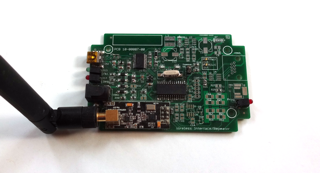
    Repeater using amplified nRF24L01+ module - makes it possible...

    Read more »

  • The Boiler

    Dan Julio08/17/2016 at 22:07 0 comments

    Nest has redefined the game of controlling a house's HVAC system - at the expense of all one's data going through a company that loves to collect personalized data about people and with no promise that at some time in the future the device will no longer be supported. Several of my friends have Nest thermostats and I talked with them about what they liked and didn't like. I came away from the conversation thinking that the most sophisticated aspects of that device are unnecessary for most people but I wanted to try to reproduce some of the features in my own system.

    First and foremost, however, I wanted to implement a safe system. My house is very simple from an HVAC perspective. Only a hot water boiler with two zones and no air conditioning. I decided to leave the existing boiler controller in place and have it see my system as a simulated thermostat. The components of my system would act as a thermostat on their own without any dependence on the greater home automation system. The final architecture was three devices. Two replacement thermostats and an interface board that went next to the boiler with relays that simulated the output of a traditional thermostat.

    I didn't want to replace any wiring which was deeply embedded in the house so settled on using the two conductors to supply DC power to the thermostats from the interface board. The thermostats then couple in a high frequency AC signal that is decoded using an LM567 analog tone decoder to drive the relays on the interface board when they call for heat. The only micro-controllers that have to work for the boiler to work are in the thermostats. There is no dependence on radio packets to call for heat. The interface board also contains a micro-controller that is tasked with watching the relays and measuring the temperature of the boiler room. Its code acts as a safety feature and it has a master "off" capability in the case where it thinks the boiler is malfunctioning (for example the thermostats call for heat but the boiler never seems to run). It can generate fault packets to the central controller.

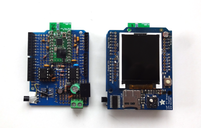
    Since this was a big unknown project for me, it ended up happening in stages and all the boards were hand wired. They used an Arduino LCD shield from Adafruit and a NRF24LE1 module from diyembedded.com. I added a new set of commands to the QualColor protocol to support HVAC functionality. Existing commands for provisioning and configuring the LED controllers were also applicable to these new controllers.

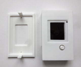
    3D-printed plastic enclosure including button nipple for 5-way joystick.

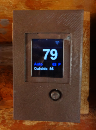
    The downstairs thermostat got painted to match the decor...


    Each thermostat is fairly stupid and has three basic modes of operation:

    • Automatic where an external controller configures the temperature set-point.
    • Manual, entered with a short press of the joystick, where the user can adjust the set-point by toggling the joystick up or down. Each night at midnight the external controller commands the thermostats back to Automatic operation.
    • Burst, entered with a long press of the joystick, that simply turns the boiler on for a short, configurable time for a quick bit of heat. Initially the burst period is 10 minutes but using the joystick it can be increased or decreased in units of 5 minutes up to two hours.

    The large display is the current temperature (since I think this is the biggest daily use of a thermostat - to see how hot it is). Under it is the mode and current set-point (or remaining burst time). Below that is a line that can be set by an external controller. Currently I alternate the date and outside temperature. Above temperature is a set of icons that indicate the thermostat is calling for heat (flame icon), is in configuration mode (wrench icon) or communicating (radio bar icon). One final line of text is displayed when the user performs certain configuration actions (such as store a new default manual set-point). The thermostat also has a provisioning mode to allow an external device to configure it....

    Read more »

  • Moving beyond LED lighting

    Dan Julio08/17/2016 at 21:04 0 comments

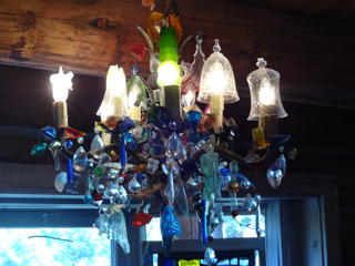
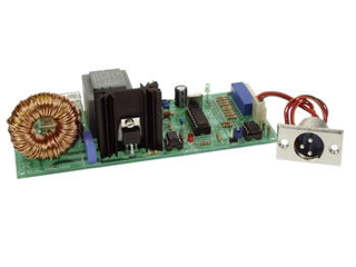
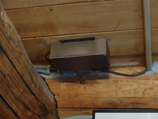
    Once the kitchen was done I wanted to control the chandelier in the dining room. I wasn't allowed to make any changes to it... so I needed to figure out how to control incandescent bulbs. Although expensive, the K8039 kit from Velleman proved to be a very good quick&dirty solution. It allows DMX control of a Triac dimmer and provided the full range of dimming (unlike some triac dimmers). I mounted the raw PCB from one of my QualColor DMX controllers with it in a custom 3D printed and painted enclosure and tried to tuck that inconspicuously away on the ceiling (how successful I was is still a matter in dispute...).

    Over time I have experimented with another Velleman kit trying to convert the LED modulation signal to a voltage to drive the kit but that has not been particularly successful. I want to design my own triac driver but haven't yet figured out the one feature of the Velleman kits I really like, that is a detection of an inductive load to shut the dimmer down before anything is damaged.

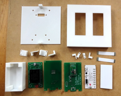
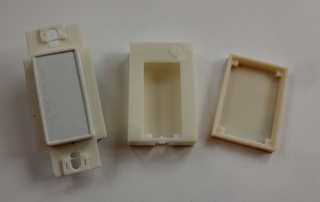
    The original wall-mounted AC switches that controlled the main kitchen lighting as well as the dining room chandelier were replaced by a custom two-gang control using two touch dimmers, two RF boards and a small 5VDC power supply tucked in the gang-box behind the 3D-printed plastic enclosure. All the parts are shown here.


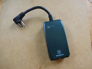
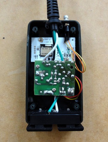
    The existing LED controllers have a feature that allows them to control a simple on/off device. If the Intensity (Value part of the HSV color specification) is zero then the device is off. If the intensity is non-zero then the device is on. This, and the fact that after one Christmas a whole bunch of wireless Christmas light relays went on sale, let me build a relay control to turn things on or off with my system. These wireless relays normally use a simple 315- or 433-MHz transmitter/receiver pair and use a capacitor power supply to provide a non-isolated voltage to power the receiver and relay. They even have a 5 volt regulator! The receiver is separate from the "power board" which made it extremely easy for me to replace their receiver with my own Nordic NRF24LE1-based controller (it only took a little sawing of the PCBs...). I used an isolation transformer during testing. Eventually I'd like to roll my own and will probably include a small transformer to provide DC power isolation at more expense.

    Currently three of these devices control various decorative lighting including strings of Christmas lights on the deck and a Mexican Jellyfish lamp in the bedroom.

    Super-cheap after Christmas!

    Replacing their receiver with my own.

    Tucked in their enclosure.

  • Foray into custom lighting fixtures

    Dan Julio08/17/2016 at 20:20 0 comments

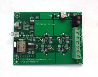
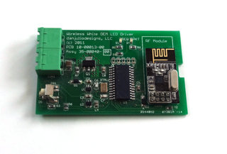
    Next up was to replace the existing halogen lighting in the kitchen with some custom LED lights. I live in a log cabin so lighting the wood itself is a nice effect. In addition to the LED spots I wanted to use some LED strip lighting to light the ceiling lumber. I hoped that would make a slightly more diffuse lighting in the room. I designed another driver board. This board now used the Nordic NRF24LE1 radio + 8051-core with new, more modular, code and contained 4 350-mA linear constant current regulators and single low-side MOSFET switch to dim the LED strips. I choose to use a linear constant current regulator for several reasons. I am using fairly high-frequency and variable modulation (a variation of bit-angle or bit-value modulation) to control LED intensity and I have seen it make switch-mode converters "sing". Some of them also have a hard time turning on and off fast enough for the changes at the low end of the intensity scale (the modulator implements some non-linear transformations to account for human perception of brightness which results in very small on periods for low intensity settings). Finally they were a great match for a 12 VDC system powering strings of 3 LEDs in series.


    The yellow wires are a modification of the constant current drivers to be slightly more efficient I figured out after I got the boards back. The boards work well although I didn't follow the RF layout instructions for the RF module and performance falls off terribly at certain frequencies. I would need to spin this board if it ever saw production.

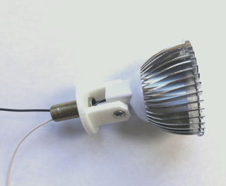
    At the time I could find all kinds of components for MR16 LED lights at dx.com and ordered a bunch of heatsinks, lenses, LEDs and LED boards. I bought both single- and 3-LED heads. I designed and 3D printed a slightly jenky custom mount to allow each head to be movable. It screwed through the base of the Chinese fixture and used a threaded pipe to screw into the overall fixture.

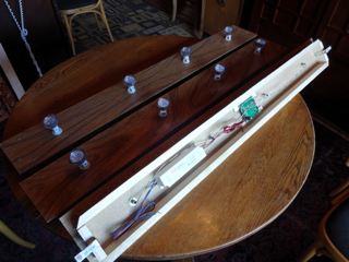
    The fixtures themselves were pretty simple. A basic wood box that contain the controller/driver and power supply. LED strips are mounted around the edge, hidden under the front surface and the LED heads are mounted on that surface. Each fixture has a 12 VDC, 5A meanwell PSU.

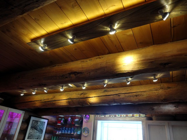
    I thought they came out fairly well. The only issue is that the "warm white" LEDs had a slightly greenish tint to them. We are used to it now but it was noticeable at first. Next time I'd pay the extra money to buy a more known device. Each fixture has its own Unit address but they all share a zone address so that they can be controlled as a single unit. A touch dimmer mounted on the wall or a remote that lives in the kitchen provide local control.

    An earlier attempt using the single-LED heads ended up more hidden over the kitchen sink.

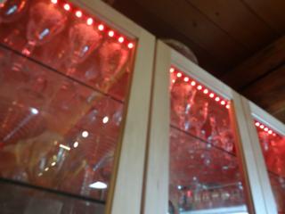
    A QualColor OEM controller drives RGBW strips in the glass-fronted cabinets and above the glassware in the corner of the kitchen as shown by this terrible photograph.


    Wireless controls are mounted on the wall and powered by a small AC adapter tucked behind the wood. The button-remote was a quick-and-dirty hack that turns out to be probably the most used control in the house. Nothing easier than pressing a button. I took some existing code and added the ability to send hard-coded packets upon a button press (and then put the micro to sleep). To change the functionality I have to recompile the code. The buttons do things like "All kitchen lights off", "All kitchen lights on at full brightness", "low brightness" and start color wash programs in the cabinets. The touch remote also controls the cabinet lighting and can be used to select a specific color if desired.

  • Moving beyond color

    Dan Julio08/17/2016 at 19:41 0 comments

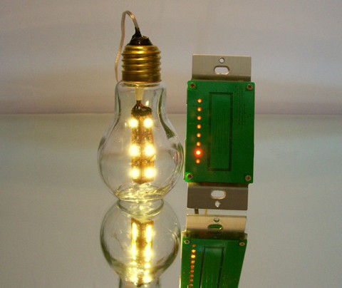
    While everyone loved to see the effects that color-wash lighting could create, in reality they wanted nice white light to live by and I ended up having interest in providing some custom under-cabinet white LED lighting systems. The idea of a wireless control was attractive because the customer could hide the receiver and power supply in the cabinets and put a remote control device anywhere. Enamored of the idea of touch controls, I designed my own linear touch control that could communicate via either the original QualColor RF interface or via a direct wired connection (I was also starting to design a set of LED controllers that would be controlled via a wired connection). My favorite part of the dimmer is a set of LEDs that softly transition in brightness via interpolation to track the finger's position on the touch control and indicate the current brightness.

    A prototype dimmer with a "lamp" made from a pill-bottle and some 5050 White LED strips.

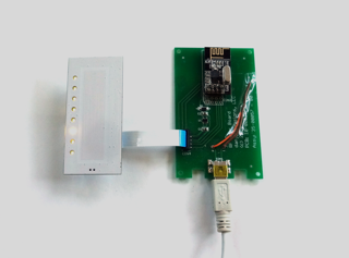
    The final dimmer board connected to a "RF rear board". I moved to White LEDs for the indicators. The micro on the dimmer PCB can communicate using the Nordic radio or a wired (serial) connection. It sends the same HSV commands but indicates that the Hue and Saturation components are not being used. This way it can control the brightness of either a white light or a color-wash fixture.


    3D printing allowed me to make a variety of enclosures for the dimmer.


    Driver board for a 12 VDC white LED strip. It was enclosed in an off-the-shelf plastic box. The button is used to "link" the device - it allows an external device to set its addresses and RF parameters.


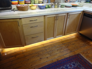
    Example of this system installed in my kitchen as a toekick light.

    At this point I decided to try to automate more of the house as an e̶x̶c̶u̶s̶e̶, er, justification to develop additional technology.

View all 9 project logs

Enjoy this project?

Share

Discussions

Rahim Khoja wrote 11/24/2016 at 19:15 point

I like the way your phone controller looks! Do you have a custom phone app for your setup? If it is an open source phone app, I would be interested in using it with my project. Do you have a git or a bitbucket?

  Are you sure? yes | no

Dan Julio wrote 11/25/2016 at 18:41 point
Thank you Rahim.  I am planning to open source at least most of this next year and will update this project.   However it's not a phone app.  It's a web server that runs on a central controller.  
  Are you sure? yes | no

Rahim Khoja wrote 11/25/2016 at 21:56 point

seems very similar to my project controller. I like the way urs looks and I think I can turn that web interface into a mobile application quite easily. When you are going to share it, please msg me, so I can try and turn it into an app for my project. 

  Are you sure? yes | no

Similar Projects

Does this project spark your interest?

Become a member to follow this project and never miss any updates