 Ted Yapo
Hardware
I couldn't detect the voltage levels used on the serial interface coming out of the meter. When I took apart the connector shell on the cable shipped with the meter to see what the heck was going on, I wasn't sure if I should be impressed or horrified:
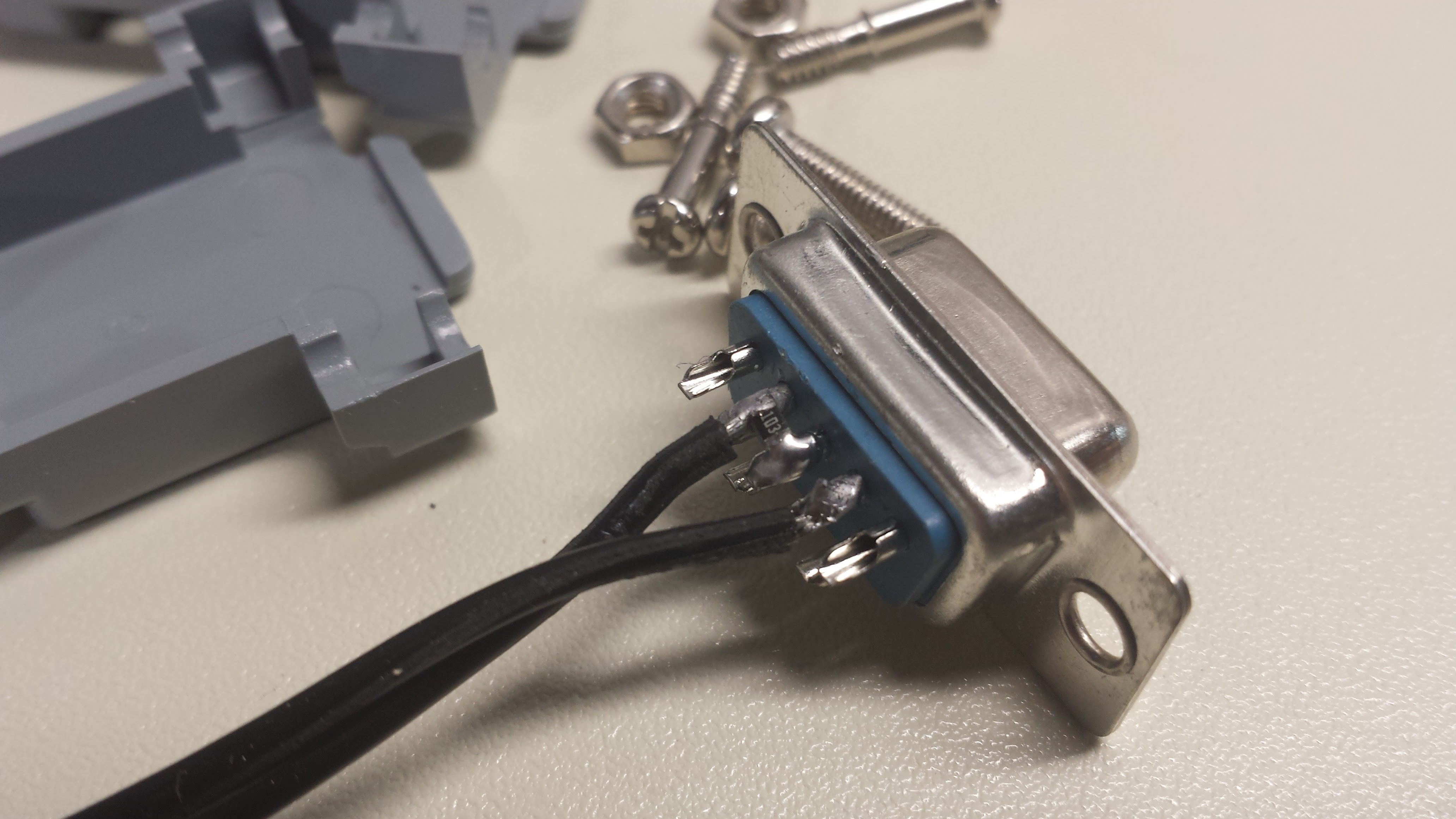
there are only two wires going to the meter. A 1k SMD resistor is soldered between the RX and TX lines as a pull-down for RX (the meter is transmit-only so TX is always asserted with a negative voltage by the host), and the DTR line (assumed held high by the host) is switched to RX by the meter to raise the signal line. Note that there is no connection to ground! This image is from the inside of the supplied cable, but you don't need to disassemble it or modify it in any way to use my adapter - just marvel at its brilliance (or stupidity).
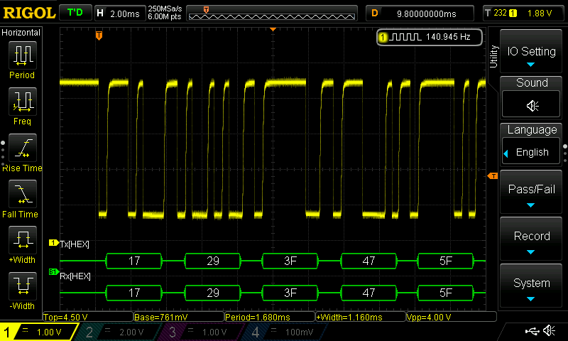
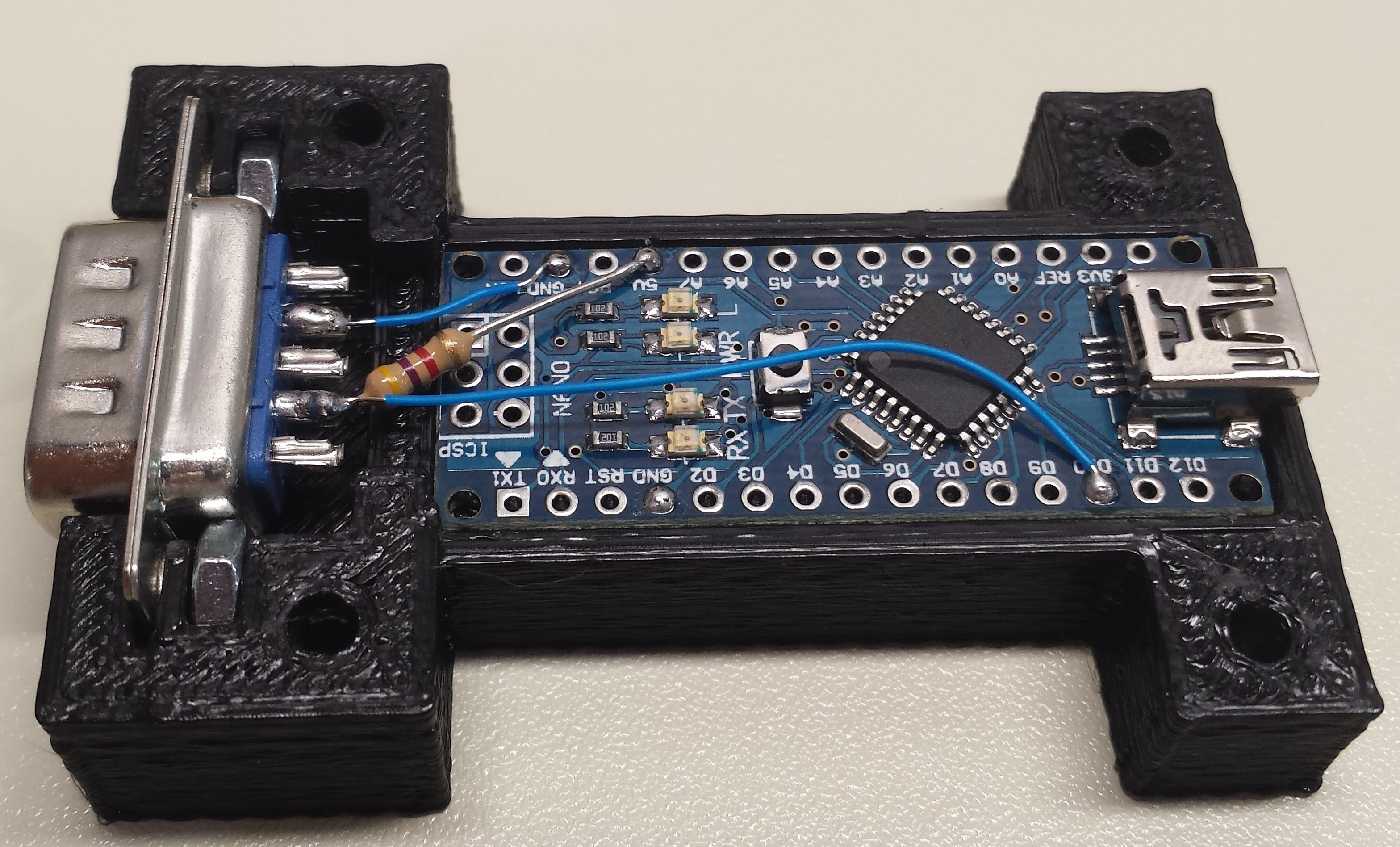
A little tinkering, and I came up with an interface to the arduino that produced nice looking signal levels:
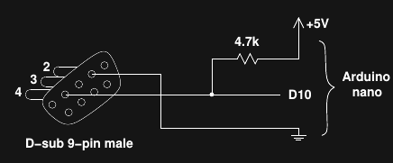
This circuit gives a good voltage swing with both copies of the meter that I have to test with. The low voltage is marginal for TTL levels, but well within the Vil spec for the ATmega328:
That's it for the connections - a resistor and three wires to the +5V, GND and D10 pins on the nano.
Case
I designed a clunky-but-functional case for the adapter in OpenSCAD. Since I already had working C++ code to interface with the meter, the case design was by far the longest part of this project. I really wish 3D printers were faster; I iterated too many times on this design :-)
Here's what it looks like in OpenSCAD:
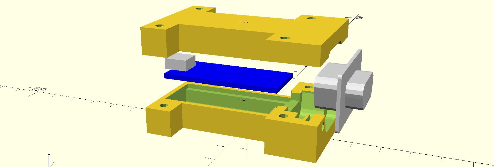
and here's the whole thing assembled into the bottom of the case:
The embedded 4-40 nuts are a little tight, but they help hold the connector in the housing. With a little force, it will all fit. The screw holes are intentionally undersized - I cleared them out with a 1/8" drill bit (you might use a 3.5mm).
Measure your nano before you print the case - I'm not sure they're all the same size, and you want a relatively close fit to keep the board from sliding around.
Unfortunately, the screws supplied with the DMM serial cable are too short to reach the embedded nuts. If you want to secure the cable to the adapter, you'll need to replace the screws in the DMMs connector shell with longer 4-40 (or M3) versions. I've decided to skip it for now, and just won't pull on the cables.
Software
I had C++ code already written to decode the crazy 14-byte protocol, so porting it to the arduino was easy. It's about 300 SLOCs, so I won't post it here - you can check it out in the repo. The code continuously receives and decodes the packets from the meter, and scans for commands from the host. Commands consist of a single byte each. I've defined three commands so far:
- 'b' : report battery-low status
- 'u' : report reading with units
- 'n' : report reading only
The responses to these commands are ASCII-formatted strings. Importantly, the adapter will only return a value that was collected after the command was received. Here's an example python program to test each command:
#!/usr/bin/env python

import serial
import time

dmm_port = '/dev/ttyUSB2'

dmm = serial.Serial(port = dmm_port, timeout = 1)

# wait for arduino to reset upon connection
time.sleep(2)

# get battery status
dmm.write('b')
result = dmm.readline()
print 'Battery low = ', result

# read numeric value only
dmm.write('n')
result = dmm.readline()
print result

# read numeric value and units
dmm.write('u')
result = dmm.readline()
print result
a typical output might be:tyapo@silicon software $ ./read_dmm.py
Battery low = 0
-2.446e-01
-2.446e-01 Volt
I formatted the data in exponential notation with four significant places, which suits the 4,000-count ADC and range of the meter. You could easily modify the arduino code to change this format or add more commands as required.Next Up
I think it's done. Let me know if you build one of these, or have any suggestions for improvement. Now I just have to print another case for my second meter.
Discussions
Become a Hackaday.io Member
Create an account to leave a comment. Already have an account? Log In.
Hello,
I’m following up on this project with a request for a favor, if I may.
I’m a visually impaired person who cannot read schematics.
If possible, can someone describe the cable interfacing to the Arduino?
Where is the 4.7k resistor connected?
Your help would be very much appreciated.
Thanks,
John
Are you sure? yes | no