 charliex
so the day started as it usually does, i installed 300ft of low voltage wiring around the house, installed some ELD 3W lights that i picked up from alixpress for $each with transformers from lowes (the equiv lights from lowes are usually around 20-30$ each ) , picked up some R G and B ones was well as the white, used warm white since cool white doesn't usually work for traditional landscaping. i spent an hour or two soldering in lamp wires since i don't care for the vampire taps , t taps or the style they sell at the hardware stores, plus they're like $5 each, almost as much as the light!
another one of my siblings came by and wanted their iphone 6 vs the 6s i did last week, fixed, so far screen swap, battery swap the usual stuff.
anyway on to the badge, i'd swapped out a npn transistor to a npn darlington, should have done a npn to pnp darlington or just bit the bullet and went back to the straight up mcu pin to npn transistor to current limit+ leds for the backlight. with the npn darlington it just wouldn't pass the current properly, so it ended up around 2.4V and flickery, if you saw me on twitter i posted about it being late, lack of sleep and possibly jumpering the wrong two pins on the transistor! so redesigned that circuit, or rather went back to original since we also decided we don't need to carry the module as well as the FPC LCD.
fitted out the battery holder, sourced that and started the new layout....again...

decided to check out different sdcard arrangement and remembered the one used on the voice, it was small and easy to repair solder ( very important at hacker cons) ,so switched to the molex 0475710001, which is cheaper, after ordering 20 for testing, then looking for a vocore dock i find strip of 50 for other projects in boxes, if we ever decided to sort out our component stocks, we'd likely be able to build a full set of badges without buying anything, it can be crazy, boxes of LEDs, i still have a box of every 0603 value resistor mouser sold about 4 years ago, and its never really been opened.
test fitted the lanyard, i always copy the holes from the previous years badges, so that is usually all good but since they're often metal clips, watch out for shorts.
ordered some more parts, we don't usually make this many prototypes, only the proxmark variant had so many built. going to reach out to a friend of mmca's in china , who doesn't speak english, but does speak chinese and korean, but apparently not for electronics and see if they can help us get the displays from taobao, most LCD modules or bare LCDs are crazy expensive from US suppliers, ebay or amazon, or even alixpress, and wading through alibaba these days is just awful, for a multiple store quote, 90% of the time its the same seller and they don't have it, and if they did its 3x the price listed.
taobao is usually better price wise because unlike aliexpress+alibaba they haven't really penetrated the western markets, so the prices are set what you'd pay in china, and not pay in the west, its a huge difference. it can also be a bit more work, depending on which store you use.
a year or two ago i saw an sms conversion, so i started to look at porting that over, it is an interesting area, since i've written many emulators over the year both for fun and professionally, last one i did was for sega to do the megadrive, so it can often limit what i want to do, better to use someone else's and just port it.
mmca wanted to change to the micro usb vs the mini, i dislike micro usb, but i accept that is the much more common cable, mini is a lot rarer for people to be carrying.
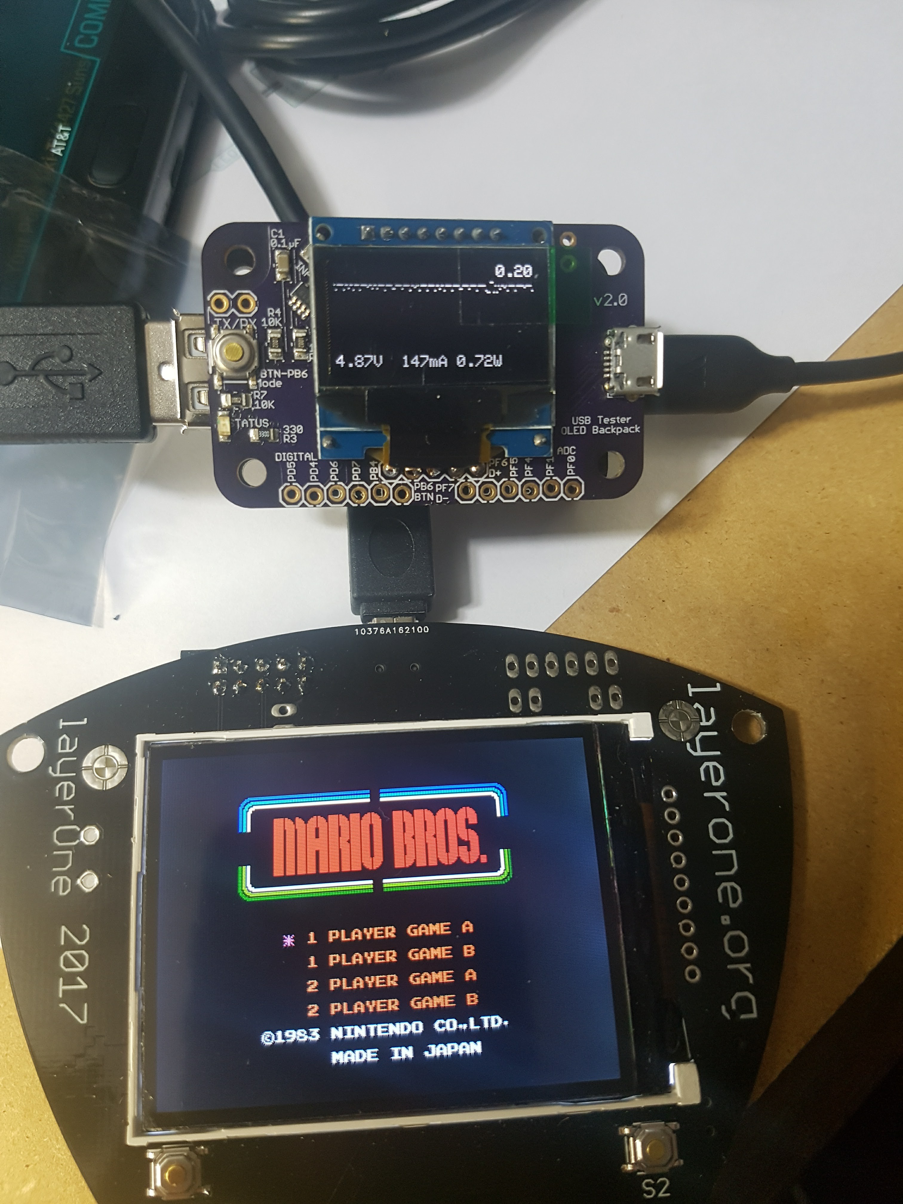
a while ago when hackaday started their store/tindie thing there was a beta, i was part of that so i bought something, it was a usb power meter something i have a few of and they're ok, but this one looked neat and i like to support people making stuff as well as HAD. so i picked it up and immediately put it in a drawer for ages, it seemed to split up between three separate drawers and i could never remember what it actually looked like, we come across it occasionally but all the parts are spread about, but as i came across a part i'd bring the, closer together. this time we actually put it together and tested it, works great ! you can even see the buttons on the USB being pressed (we're over-driving the back-light here hence 147mA)
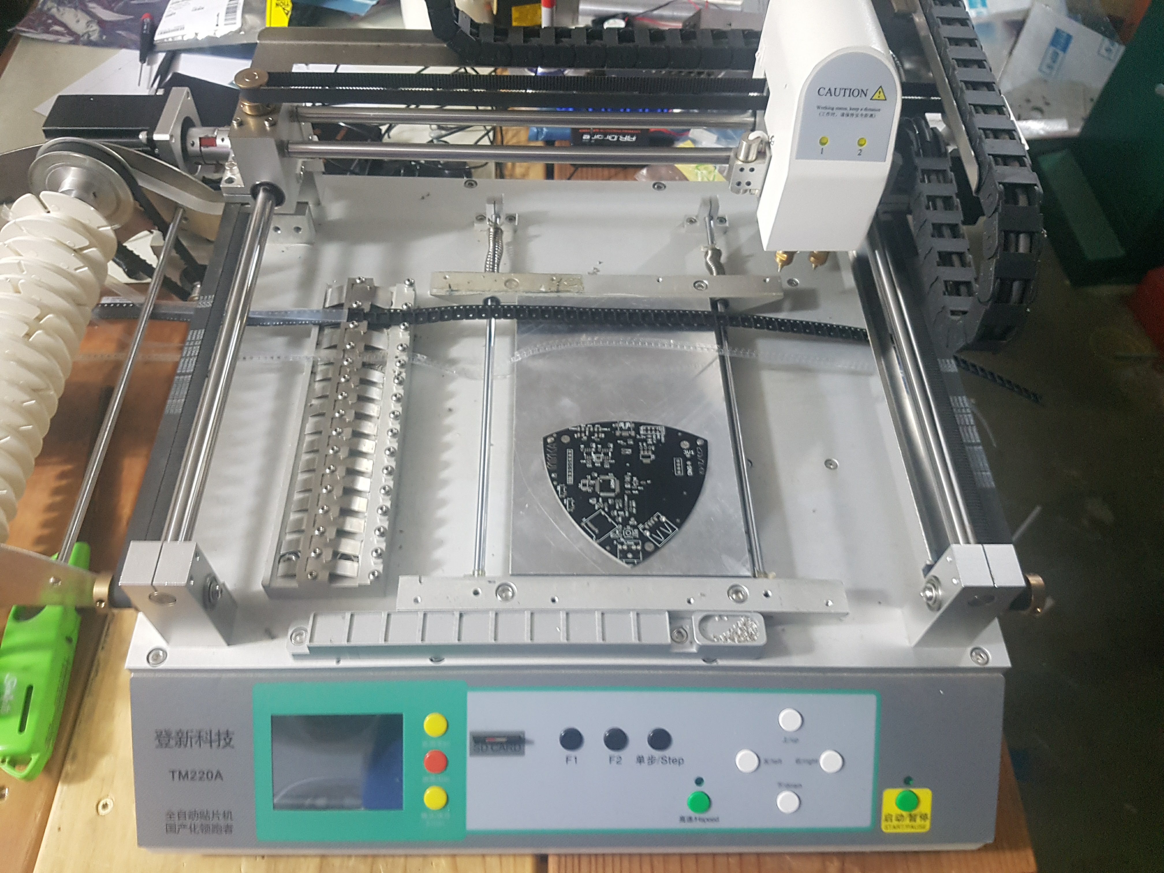
we also started to setup the pick and place and think about how we'd mount this shape of badge, normally we do a palette with locating pins out of tool plate, that has worked well in the past since we don't place a lot of components usually, this year we're trying to maximise it. this causes another issue since the spent reel plastic has to go under the board and eject from the other side, our tool plate gets in the way, so its going to be a cut out PCB this time, which is less great.
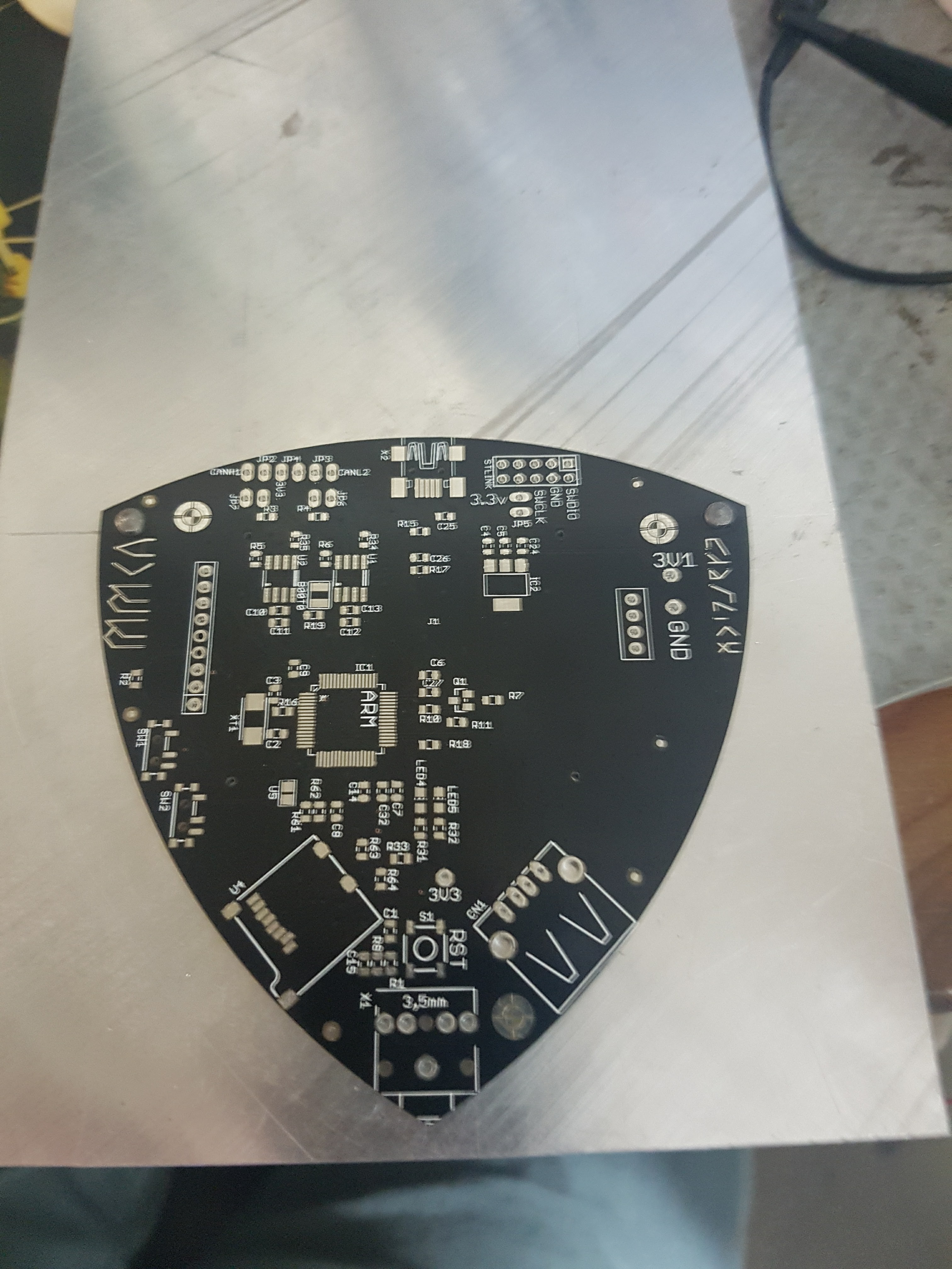
by the way, if you are doing hand assembly, especially with a lot of people, silkscreening the text from the CPU is a great idea, the little circles are terrible and inconsistent, fine for auto place, but less so for people
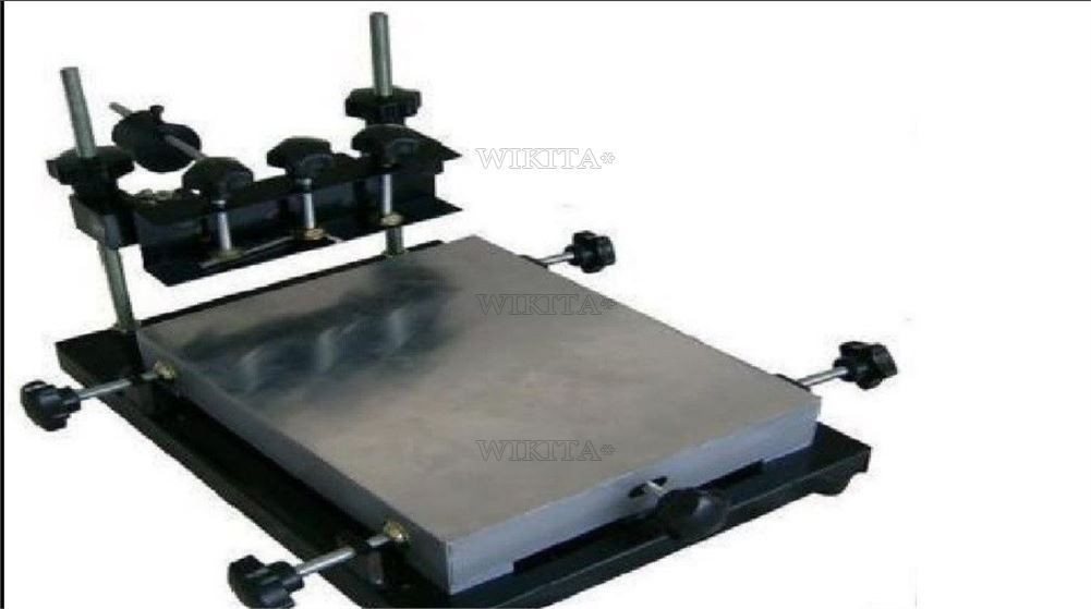
i did order a stencil holder this year, we typically just fab one up and it is OK, they're not expensive and its a good investment for future. stock ebay photo, it hasn't arrived yet.
we typically build two of the new prototypes and i'd been spending a lot of time on the graphics/emulator sides of the badges so i decided to hook up CAN and see if all was OK. all was not OK, no messages or very slow output, and i'd even remembered to save a known working firmware and check it in for.
again the 235 ended up on the board, but i'd thought about it and added the extra hardware for it, so was it that again, no? missing grounds, all seems to be good? xtal? nope not used in this example, try an older prototype, works great. do the old touch the pins and see what happens, nothing really, but then i notice as mmca is plugging it in to usb it leaps into life for a few seconds. so badly soldered, still no? so what is causing it to work capacitance, something loose? pressing the chip surface and not the pins, works better, triple check the soldering, still nothing, pressing again.
More checking, one of the pins appears to be loose in the package internally! swap out the chip and bingo works, the shame part is that the LCD is likely recrystalised so different colouration/polarisation with the number of reheats to track it down. it can be so hard to keep "pretty" looking prototypes.
bad chip , what are the chances, especially since it made it look like an issue we have seen before.
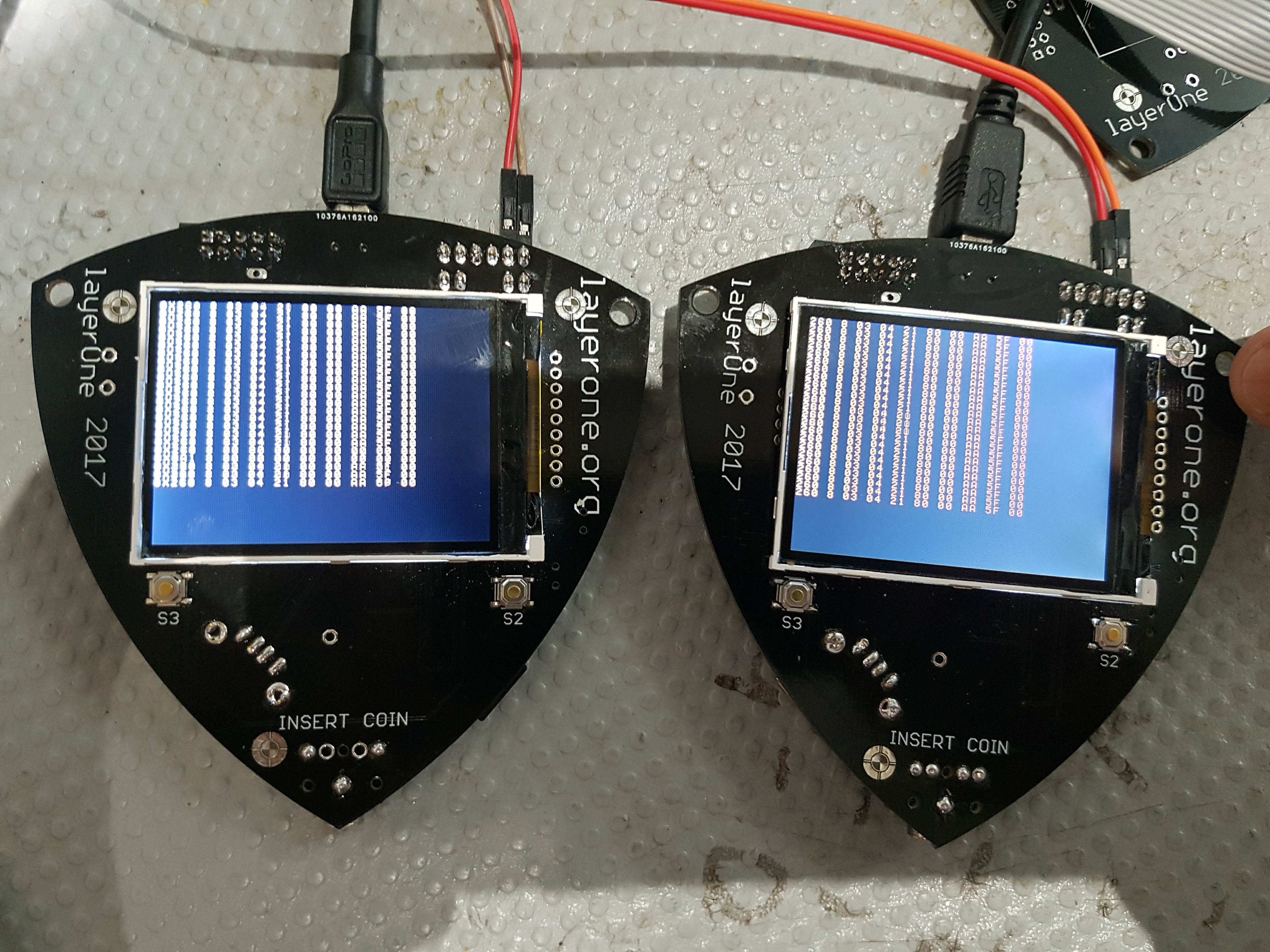
anyway, here they are both connected to a CAN bus watching one of my bench ECUs its not a particularly useful demo since it flies by and it is better suited to being output to USB or SDCARD but its a good visual test that it is working. I'm using a simple mbed project off the shelf here, interrupt based CAN capture, writes into a wrapping text buffer and prints them out as a loop.. but quick and easy.
very basic, short as possible doesn't usually include memset, sprintf (snprintf!!) and modulos
/**
 * @brief   'CAN receive-complete' interrupt handler.
 * @note    Called on arrival of new CAN message.
 *          Keep it as short as possible.
 * @param
 * @retval
 */
void onMsgReceived()
{
    CANMessage msg;

    memset ( &msg, 0, sizeof ( msg ) );

    if ( can.read ( msg ) ) {

        sprintf(buffer[index%NUMBER_TEXT_LINES],"0x%03x %d %02x %02x %02x %02x %02x %02x %02x %02x", msg.id,msg.len ,
                msg.data[0], msg.data[1], msg.data[2], msg.data[3], msg.data[4],msg.data[5], msg.data[6], msg.data[7]
               );
        index++;
    }
}
but just to show how easy it is to setup
CAN can(PB_5, PB_6); // CAN RX pin name, CAN TX pin namethen later something "like" this
void foo(void)
{

// baud rate
   int  error = can.frequency(500000);
    if(error == 0) {
// do something
    }

// mode if supported
    error = can.mode(CAN::Silent);
    if(error  == 0 ) {
// do something
    }

// monitor mode
    can.monitor(true);

// filter if used
//  filterhandle = can.filter(0xff,0x07ff,CANAny,0);

// attach to the interrupt routine
    can.attach(&onMsgReceived);
}
and that is it, with that you're capturing code and since it is mbed online no compiler needed.
i'll start to add more code as i go along and also not edit it in the project log so it'll be as is.
this week i do hope to be doing more interesting stuff and do some updates on the CAN side software and what the badge is meant to do !
here is a more or less completed prototype with yes actual box headers for a programming connector.. one of the CAN busses connected and shared between both badges, jumpers for the 120 terminating resistor.
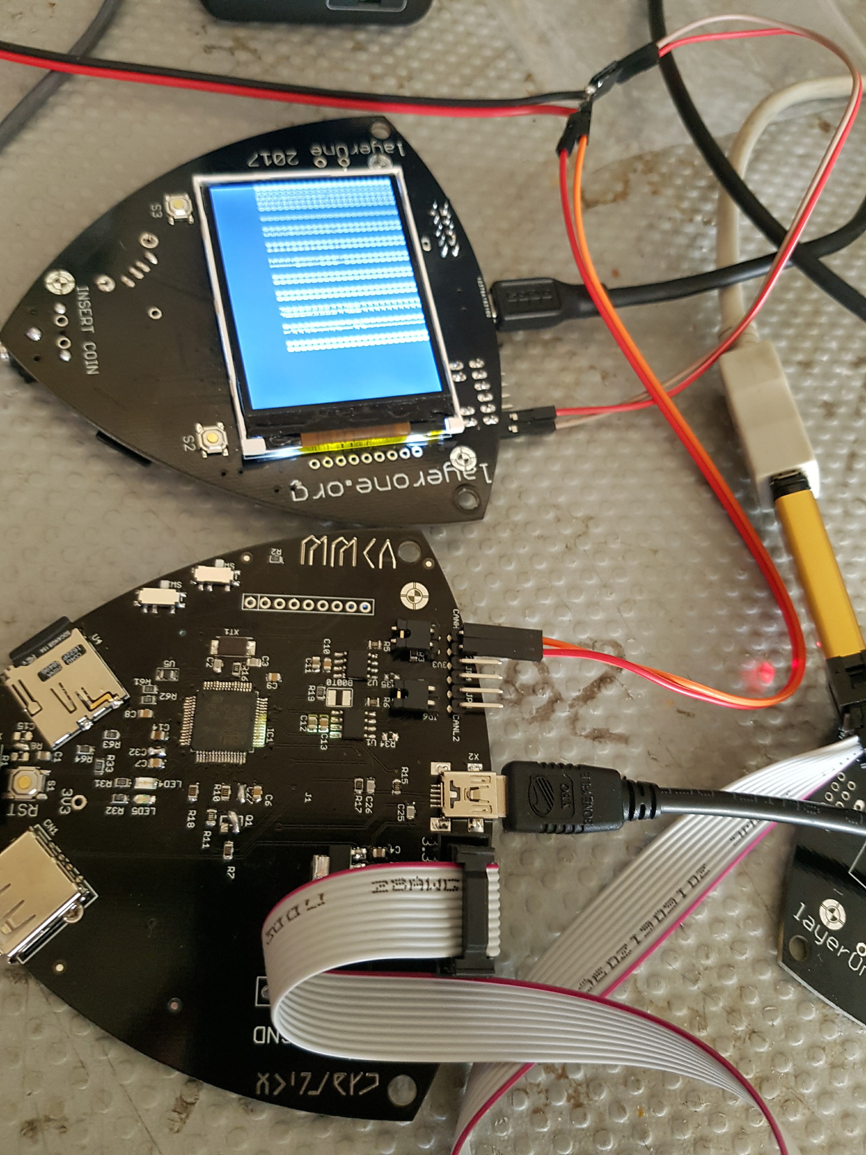
it is almost there, last part is the battery which we're waiting on some parts changed in the eagle files, routing and then send it off. and the battery charging chips to be delivered.
now since the rest of the family is having a great time at disneyland, i'll crack on with this and installing the rest of those outdoor lights :)
cheers
Discussions
Become a Hackaday.io Member
Create an account to leave a comment. Already have an account? Log In.