Aractapod
-
This Is Just A Test: Breaking Things
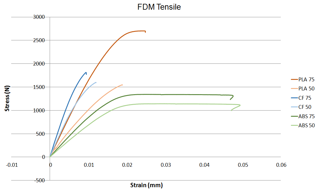
09/14/2016 at 23:34 • 0 commentsAfter printing the test samples the group used an Instron testing machine to gather data about the tensile properties of the proposed materials. Drawing the sample at 2.5mm/min provided valuable data about the materials being used in this comparison. The tensile data gathered shows the stress over strain curves for the six samples tested. The group concluded that the PLA sample tested at 75% infill provided the most strength, but proved to be very brittle.
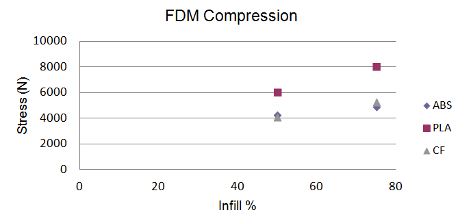
With the tension data gathered the group continued to research the compression characteristics of the materials. Due to not having the proper fixtures needed to test compression on the instron machine the group was forced to use a hydraulic compression machine. This machine utilizes hydraulic pressure and manual controls to modulate the testing surface. The data gathered from testing on this machine provided the group with only the maximum compression values of the samples.
The compression data again proved that the PLA material printed at 75% infill was the strongest. Using ABS allowed the group to print more durable models in a very short period of time, which was the most ideal choice when choosing a material.
-
Deciphering The FDM Code
09/14/2016 at 02:36 • 0 commentsTo fabricate the model to the level of detail needed the group chose to use rapid prototyping. Using rapid prototyping allowed for us to make quick revisions and produce parts on a much cheaper scale than other forms of prototype manufacturing.
Understanding how 3d printers work is crucial to the group being able to feel comfortable in leaving a part to print for 10-12 hours and not having to worry if the part will fail. This was done by first ensuring the machines were calibrated correctly by using a standard 1 cm x 1 cm cube and measuring after it prints. The group then printing a variety of different objects in order to understand how 3d printers work.
The group discovered that by using a method of hexagonal slicing to create the internal geometry a partially hollow center known as infill was created. Using an infill allowed the part to be sturdy, lightweight, and print relatively quickly.
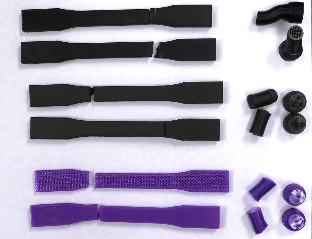
One of the biggest problems we discovered through testing and playing with printed parts is that the parts need to be printed in a way that allows for the forces to be subjected to the material in the direction axial or parallel to the layers as the separation between layers is the most vulnerable to breaking. As can be seen in the CAD files (located in the files section) and picture below, the group created tensile and compressive test samples in order to help understand the material properties of 3D printed parts.
-
The Material Challenge
09/11/2016 at 16:14 • 0 commentsThe group started its research by searching for how current prosthetic feet were being analyzed to find potential problems that could be solved. This initial research posed several questions to the group. Was carbon fiber truly the best material for a prosthetic foot? Were than any alternatives to carbon fiber that would be both less expensive and provide a stronger more resilient structure? Is there a way to make the foot more lifelike to provide a more natural walking gait? Would a change in material help the walking gait become more natural? These questions were noted and kept in the back of everyone’s mind as research continued.
Also throughout the group’s research the discovery that options for materials that are used to build the structure of the prosthetic foot are very limited. The major choices are carbon fiber, titanium, steel and aluminum. Each of these materials have their downfalls. For example, carbon fiber and titanium are both very expensive, but are the strongest options currently available. Steel is relatively cheap and very strong but to heavy when too much of it is used. Aluminum is cheap and lightweight, but not strong enough to support a human when it becomes too thin.
The group has also done a fair amount of research into 3D printing and have decided to prototype the final design using FDM.The group will run a feasibility study on whether 3D printing could be a future option for the manufacturing aspect of the project.
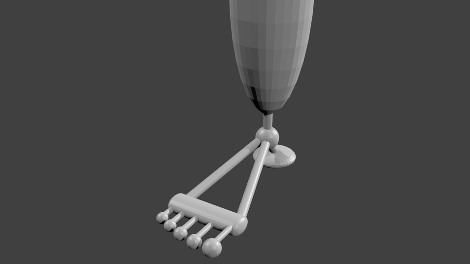
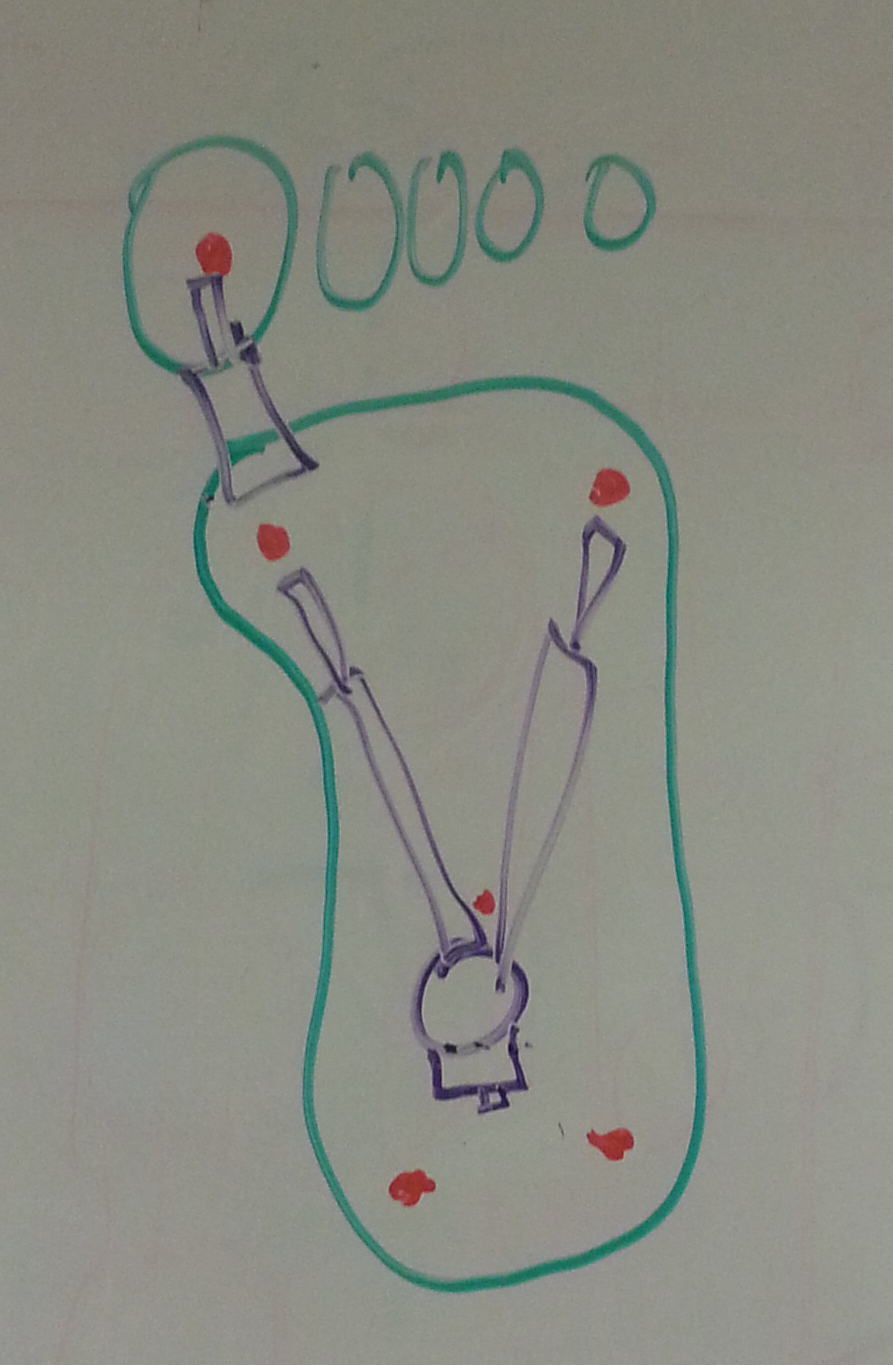
To accompany the research being conducted a line drawing and generalized foot structure were created to model a universal human foot:
Going forward we will work on the materials study while testing our generalized model, to find what material is best for our application.
-
Brainstorming
09/09/2016 at 02:39 • 0 commentsIn order for the group to figure out what our initial steps in designing a prosthetic foot are going to be we must brainstorm. Below is the brainstorming that we did in order to figure out the direction we would like to take this project towards.
Aluminum vs. Plastic Materials vs. Composite
Structure Shape and Mechanics
Hydraulics vs. Pneumatics vs. Motors
Rotary Joints vs. Pin Joints
Form and function to improve walking gaitAfter completing our initial brainstorming the team has now decided to pursue the following as our direction for the prosthetic foot design.
The project has been broken up into multiple pieces those being:
Mechanical Structure Design
-The mechanical structure of the prosthetic foot will be designed and initially tested using 3D parametric modeling extensively. A material study will be done in order to choose which material will be best for this application.
![]()
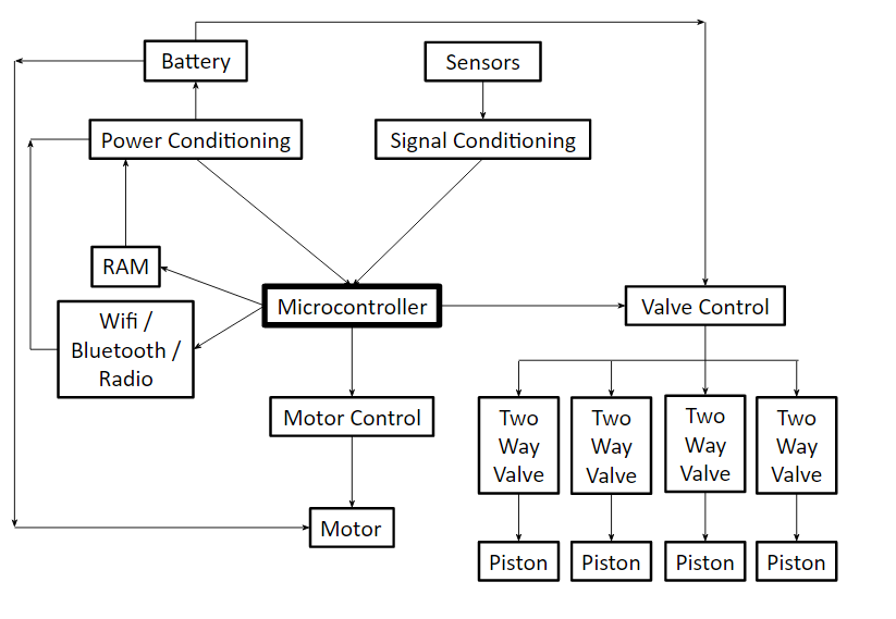
Microprocessor based controls
-The Arduino software platform will be used in order to control the electronic components of the prosthetic foot
![]()
Power System Design
-The power actuation of the foot will be accomplished using micro-hydraulics. Some of the components include a pump, recevoir, valves, oil, and tubing.
![]()
Testing Equipment Design
-Testing equipment will be manufactured in order to test the sub components of the system
Mechanized Prosthetic Foot
The purpose of this project is to design and build a fully mechanized prosthetic foot that is more accessible than current solutions.