 Yann Guidon / YGDES
My logs about speeding up the 2N2369A have brought a lot more of insight or CDC's RTL logic, as well as confidence in my methods, and the results are very good. So the next step it to explore the following technology node : ECL.
One defining angle of my exploration was not much the absolute raw speed but about finding the "sweet spot" where a small increase in speed was not at the cost of a large increase in power. I want to apply this angle to ECL as well and see if/how I can reach a similar (or better) speed/perf ratio.
I will use a similar method as the 2N2369 : measure the RingO9 speed so the data can be easily compared. In the beginning however I will use Silicon transistors, for 2 reasons :
- If I use 2N2369As again, the comparison of the topologies is easier.
- Flastad's sim has no germanium transistor in his models
Another question is where to set the power supply voltage. Early sims show that I can get down to 2V easily.
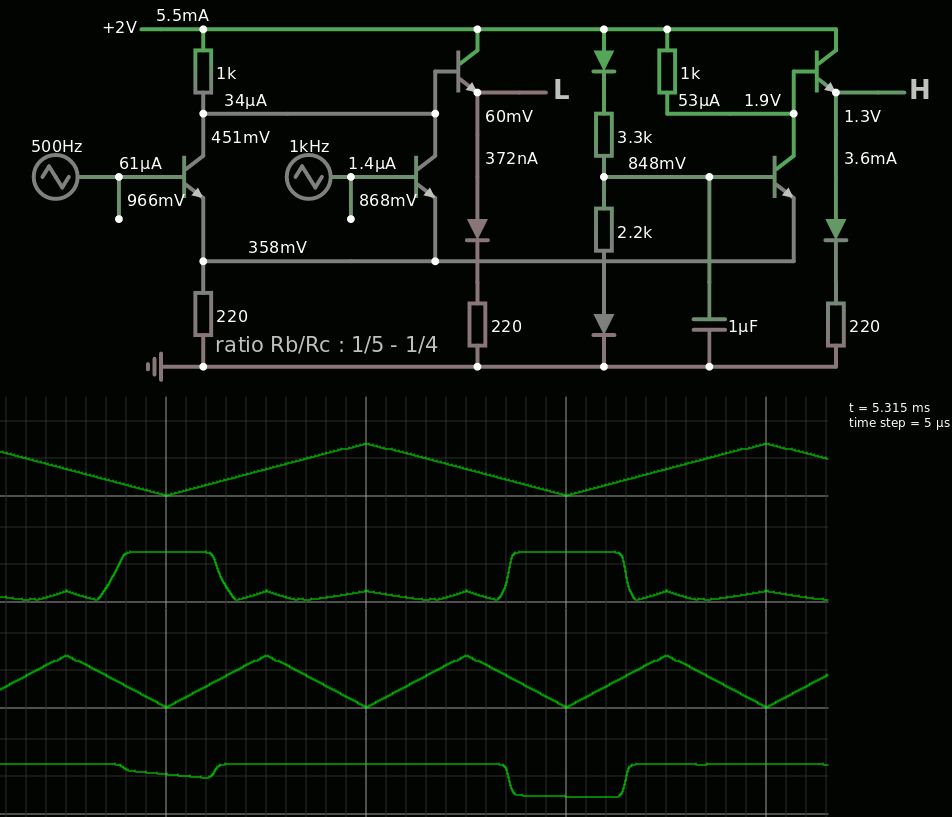
(yes the ref's capacitor takes a while to load)
Then I found that more tweaking can occur :
- reduce the resistors
- if fanout is 1 then drop the common collector output drivers and just drive the next stage directly
- fine-tune the Vref
And I can reduce the supply even more to 1.5V. The tuning parameters become the Vref and the common low-side resistor. Here are 2 examples with 2 values :
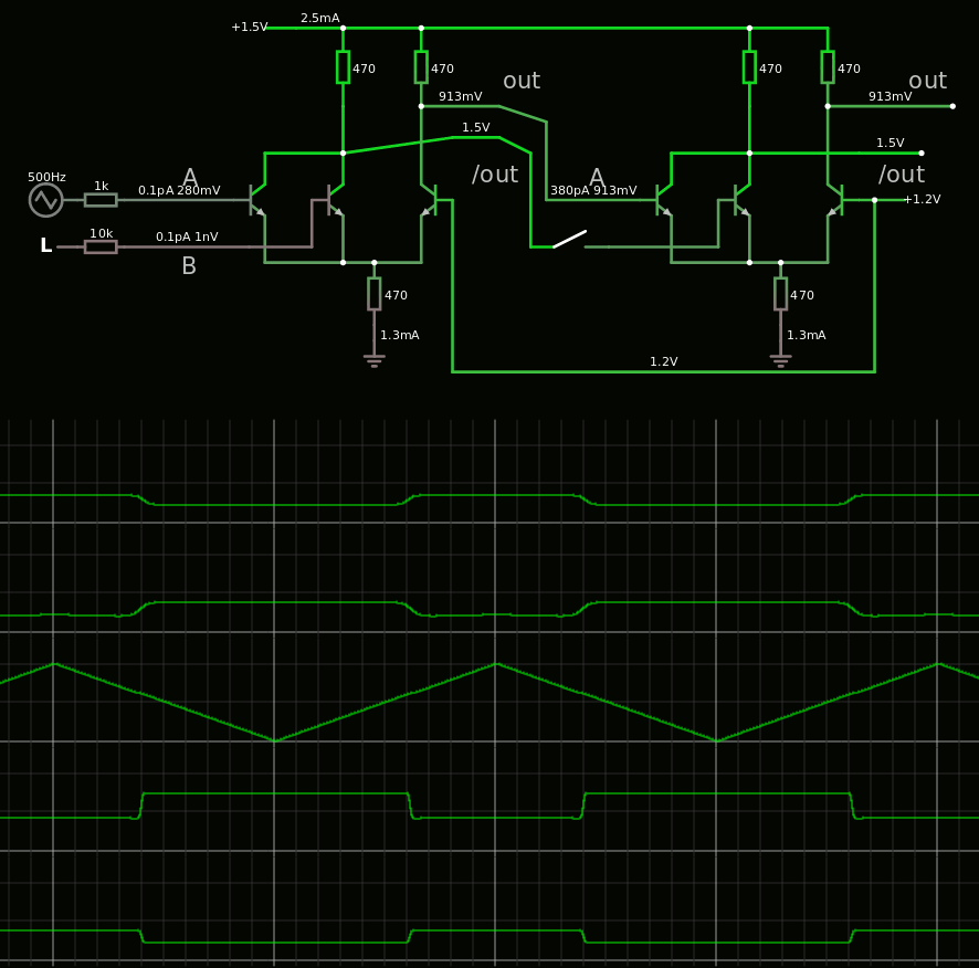
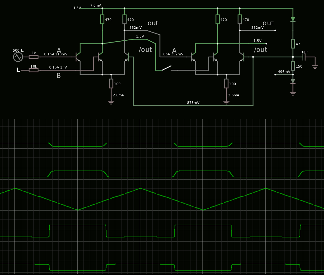
When the common resistor is lowered, this increases the current but also the swing so the Vref must be adjusted.
Looking at some 5V schematics I see the pull-ups at about 50-300 Ohms, and the common resistor at about 300-1K. Here I have reversed the ratios but starting from 470 Ohms lets me compare the topologies with the CDC-RTL that uses the same value.
Increasing the common resistor might increase the sensitivity but also reduces the current/slew rate (supposedly) while at the same time reducing the swing (is that good or bad ?).
Another aspect of this approach is that we are confined to only single-layer types of gates : no series-dotting and the associated functions. It's (N)ORs all the way down, like with RTL. But each ECL gate has 2 complementary outputs so each count as 2 RTL inverters !
Series-dotting brings more logic functions to the table though. Latches and XORs are essential 2nd order circuits that are dearly required.
A non-insignificant part of the consumed current comes from the voltage reference. The typical circuits use some sort of regulator... I am now wondering how I can reduce the current while keeping the minimum number of parts. At this moment I think of a transistor on the high side (collector and base tied to make a diode) and a pull-down resistor (value TBD).
So we can start with this rule-of-thumb : each layer of transistor is separated by a diode (Vbe) drop. This keeps the regulator simple yet with low impedance.
A few sims later and I get this inverter design :

Vref is at 1.5V : there is only 0.5V drop in the transistor but only 130µA is drawn. This can be tuned with a potentiometer tied to the ground.
The signal swing is 1.3-1.8V : +/- 0.3V around Vref, nicely symmetrical :-) I had to tune the upper resistors a bit and it's good.
Surprisingly, and I couldn't guess from a test with an individual gate, the current of the 5 gates is only 9-12mA (2mA/gate ? :-) ) so decoupling will not be hard.
With 390 ohms and the emitter going from 0.85V to 1.2V, the base current swings from 0 to 0.5mA so the transistor is barely saturated : no need to fight hard to drain the base charges...
The 470 Ohms common resistor goes from 0.85 to 1.2V, that is 1.8 to 2.5mA, or 2.2mA average. A transistor-based current sink would be appropriate to reduce the current variations and the PSU noise.
Discussions
Become a Hackaday.io Member
Create an account to leave a comment. Already have an account? Log In.
Very interesting project! I'm also planning on doing some ECL circuits, but from silicon. Looking at your inverter simulation, the input transistors saturate. Doesn't that slow down the gate?
Are you sure? yes | no