Now I'm starting on the graphics board. As I mentioned in my previous post there will be two main parts to it. Ginger, (probably designed around an 8mhz Atmega 162) and Mary Ann (again, another 8mhz Atmega 162).
Ginger will read the display list sent from Gilligan (the 6502), change it into tiles, sprites, etc. and then wait for VSYNC. When she gets VSYNC she'll copy the first set of tile and sprite color data to scan line buffer A. Then, when she gets HSYNC she'll populate the next line on scan line buffer B. She'll continue doing that alternating between scan line buffer A and B throughout the entire frame. In essence, Ginger is always preparing the scan line buffer for the next line to be drawn.
Meanwhile, Mary Ann is our work horse. She'll be responsible for maintaining the composite sync pulses, grabbing the color data from the scan line buffer for the current pixel being rendered, and loading it into shift registers for the composite out.
Why shift registers? Well Mary Ann will run at 8mhz, this is not fast enough to load a color from RAM and write it to the composite output each pixel.. I won't get into NTSC timings at the moment but with the resolution we're running at I have approximately 10.5us to have each pixel displayed.
So I will have 4 8 bit shift registers which will output the line of a tile. Each of the 8 bits will be a pixel in that line. The 4 registers will represent colors, 1 register for the red pixels, 2 for the green pixels, 1 for the blue pixels. This will allow me to output 4 bit color in the form of RGGB (I posted the possible colors this will display in a previous log entry).
To say this another way, each shift register represents a color channel (R, G1, G2, or B) for the 8 pixels in the current line of a tile. Each register consists of 8 on or off bits, each bit representing whether the color channel is active or not for each of the 8 pixels. For each pixel, the video clock pulse will cause the register to shift the next bit out. If this bit is on then voltage will be sent to its respective color channel pin on the composite video chip and that color will be on for the pixel, otherwise it will be off.
Technically I'll have two sets of these registers (A and B) so Mary Ann can be filling one set with the next tile while the current set is outputting to the composite video chip.
Anyway - that was a long way of saying I'm going to start with Mary Ann first, I figure she will be the most difficult part of the project because of the video timings. Here is a picture of the current version of my schematic (which will most likely change many times as I figure things out, you can also download the dch file on my github):
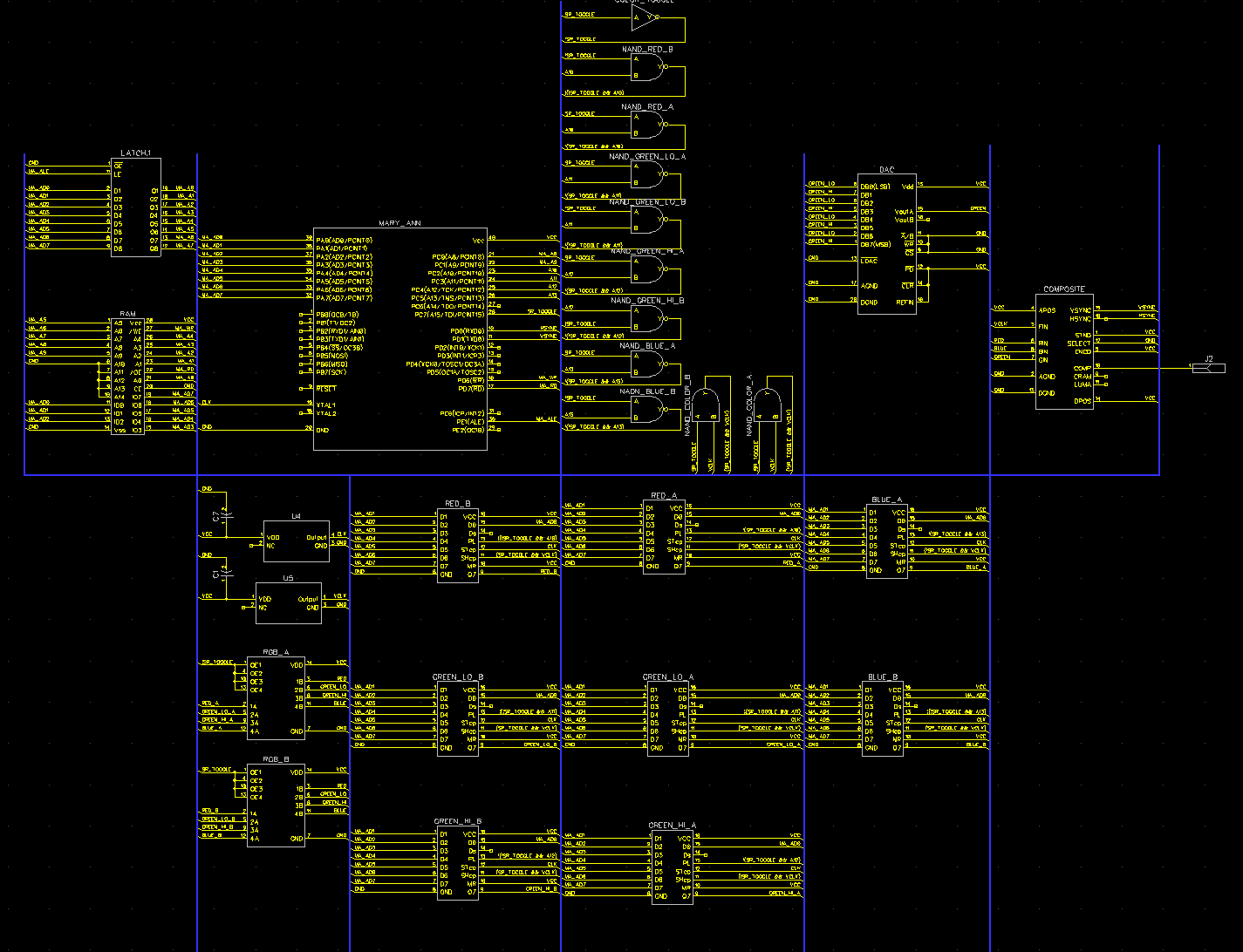
To start with, I'm going to simply wire up Mary Ann talking to the composite video chip so I can get the timings and ASM code working correctly - my goal is for her to output red, green, and blue color bars.
My current plan is to use an AD724, as I understand it I'll still need to provide HSYNC and VSYNC timings, but it will handle the color burst required by composite video. I'll update the log when I've done a bit more research and ordered my components - hopefully before the end of the week!
Discussions
Become a Hackaday.io Member
Create an account to leave a comment. Already have an account? Log In.