 Beaglebreath
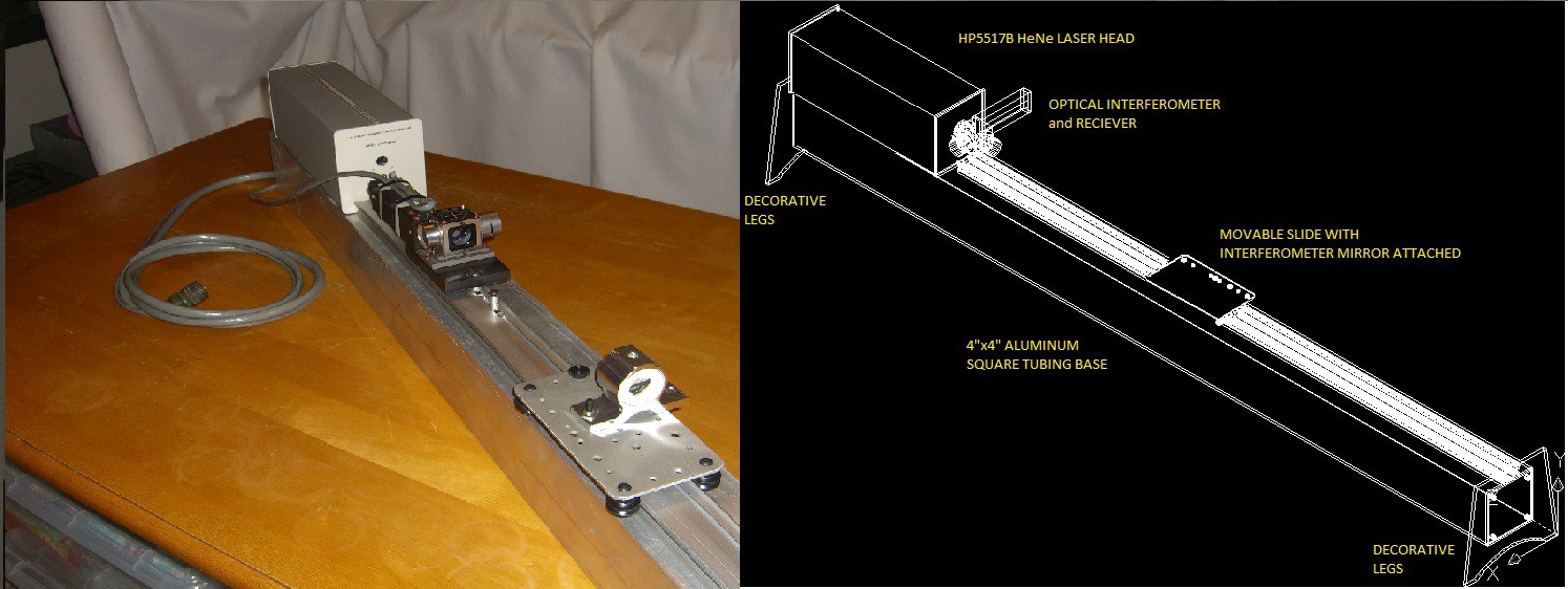
here is how the construction of the interferometer has gone so far. I cut the 4"x4" tubing from a 10 foot section of spare tubing that I've had in storage for about ten years. It was cut off using a router and straight edge. I drilled a set of holes to mount camera slider rail. The "Simple Camera Slider" was ordered with a bunch of extra nuts and screws and other hardware. The extra hardware came in handy as I was trying out every possible way to put the parts together.
 The final arrangement of the receiver and the 1/4 wave plate was changed from the way I originally planned. In the photo above the laser beam leaves from the laser head, and then skims past the side of the receiver, then into the beam splitter. I could not get the arrangement shown in the CAD drawing to work. That was too bad, since I had also designed a mounting plate to hold all of the interferometer parts stationary relative to each other.
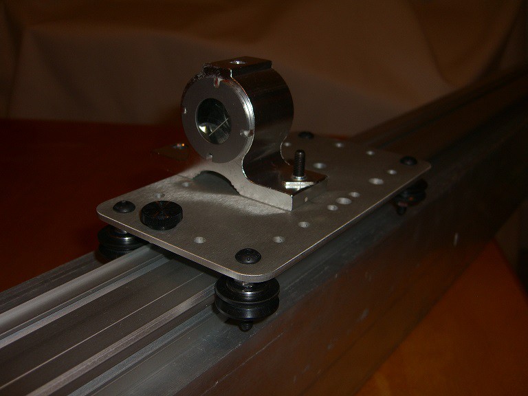 Above is a picture of how the slider is going so far. The retro-reflector is the mirrored object. It has a flange for mounting it still. I had a leftover conduit clamp which was a close fit to the outer circumference of the retro-reflector body. I wrapped a scrap piece of wool around the retro-reflector body, and slipped it into the conduit clamp, and now it is held steady enough for playing around with different ideas, until I get this project built in a way that works the best.
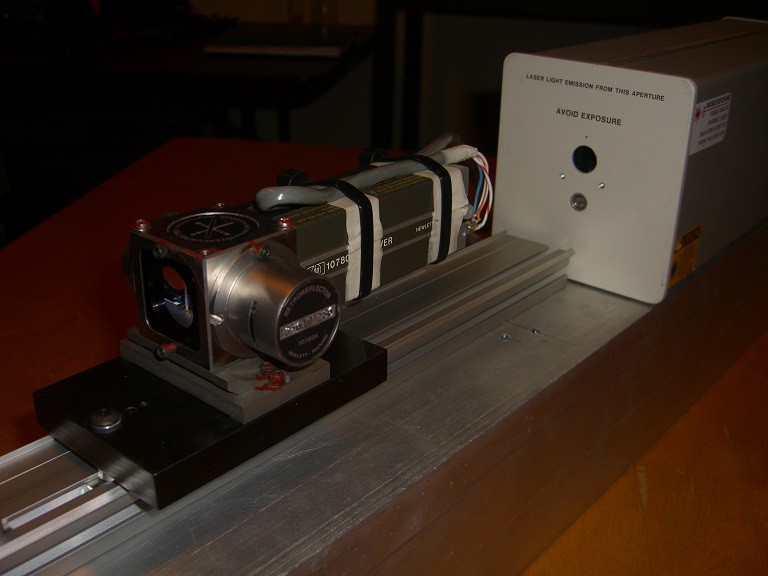 Above is a view from the opposite angle as the first picture. All of the optical components are from ebay trappings as well as the receiver and measurement display unit. The laser head was purchased from the proprietor of repairfaq.org It is a completely functional laser head, with low mileage and lots of cool warning stickers.
The cabling between the 5508A measurement display, the laser head and the receiver was a DIY project which eventually took two days to complete. The Mil-Spec canon connectors are not standard off the shelf. For some unknown reason the arrangement of the 18-pins in the body of the connector is different than the current connector available from my distributors. I ended up buying two of the ones that are available and pulling the pins and internal rubber guts from the connector. I then had to rotate the relative position of the body, then reinsert the pins. I then started burdening repairfaq.org with 50 questions about how to wire the three components together. His summary of how to build the cable is given here ( http://www.repairfaq.org/sam/laserhst.htm#hst5508x1 ). After soldering the connectors using a 25 foot section of 18 conductor cable, I added a second 4-conductor cable to the connector on the 5508A side. The receiver also has a weird connector. The connector has a BNC style shell, but has four pins on the inside. Two are male, two are female and the nylon spacer is an interlocking style. I could not find the connector part number in any searches so far. I ended up using male and female insertion pins from a couple db-25 connectors. After I wrapped the exposed pins in masking tape, I pushed them in place in the reciever connector and glued them in place. The wire ties shown in the picture above steadies the assembly as well as giving a good strain relief for the wiring.
Discussions
Become a Hackaday.io Member
Create an account to leave a comment. Already have an account? Log In.