 Kris Winer
May 8, 2018
It took me quite a while to figure out how to get the firmware loaded onto the SPI flash. The easy part was dragging and dropping the binary firmware file I downloaded from the AMS download site onto the QSPI flash of one of my Dragonfly development boards. The QSPI flash can be chosen in the Arduino IDE to emulate a disk drive on Windows machines (maybe others as well) so I just dragged and dropped and then the firmware was on the Dragonfly QSPI flash. Easy peasy!
I wrote a little program to attach the QSPI flash as a DOSFS (FS.h) object but could not get the file to open. All of the other firmware files (for the EM7180) showed as FW type with the .fw extension and these would open just fine, but not the binary type file with the .bin extension or any other extension I tried. I tried opening the files with Notepad and Wordpad, saving as generic files, and then loading these onto the QSPI flash. While this allowed opening the files with DOSFS the files were corrupted and no valid firmware was actually written to the 512 kByte SPI flash on the AS7265X board. Finally, I opened the firmware with ProXoft's BinaryViewer, selected the entire contents, and saved this to a generic file and, lo and behold, I got a FW type file with a .fw extension that I was able to open with DOSFS. By comparing the bytes read back from the 512 kByte flash and the bytes read with the BinaryViewer I convinced myself that the firmware was written to the flash correctly.* Whew!
The AS72651/2/3 will blink their indicator leds when they have no firmware or incorrect firmware (the rgb led proved to be a useful diagnostic) or when they are not soldered properly (or in reset mode for the same reason) as I also found out. Before the firmware was flashed, all three of the leds were blinking resulting in a rainbow of colors. Once the firmware was finally successfully flashed, I saw a red led momentarily flicker on power up and then just a green led flashing twice a second. The red led is the AS72651 successfully downloading the firmware from the SPI flash. The green led, it turned out, was the AS72653 in some distress. I think there was a cold joint on the nRST pin since I didn't see any solder at that location. I just reheated the board, tapped on the AS72653 with my tweezers and tried again. This time, just the initial red light and then nothing...just what I was hoping for!
I then scanned for I2C devices but saw nothing. Now the AS7265X devices aren't true I2C devices in that they have a virtual I2C interface. I am not sure what this means but I decided to try the UART interface instead of spending hours writing a program to read and write to the virtual registers and verify function. I will do this eventually anyway, but I was anxious to know if my board was alive or not.
I connected a 3V3 FTDI connector to the board using the FTDI's 3V3 and GND for power. I had to use a jumper to connect the I2C enable to GND to get the board into UART mode. All of this worked well (despite the 4K7 pullups on the I2C/UART bus) and I was able to get the right COM port in the AMS-supplied GUI and verify that 1) firmware version 1.2.7 was indeed loaded onto the flash and made its way into the AS72651, 2) the broad band led produced a blinding white light at the 12.5 mA setting (but I couldn't see the 850 or 940 nm light from the other two illumination leds to tell if they are working), and 3) the AS72651 and AS72653 smart spectral sensors are working! I was able to take data which varied as I moved the sensor around. Unfortunately, The AS72652 showed 0XFFFF for all six channels and does not seem to be working. Here is what the data I took looks like:
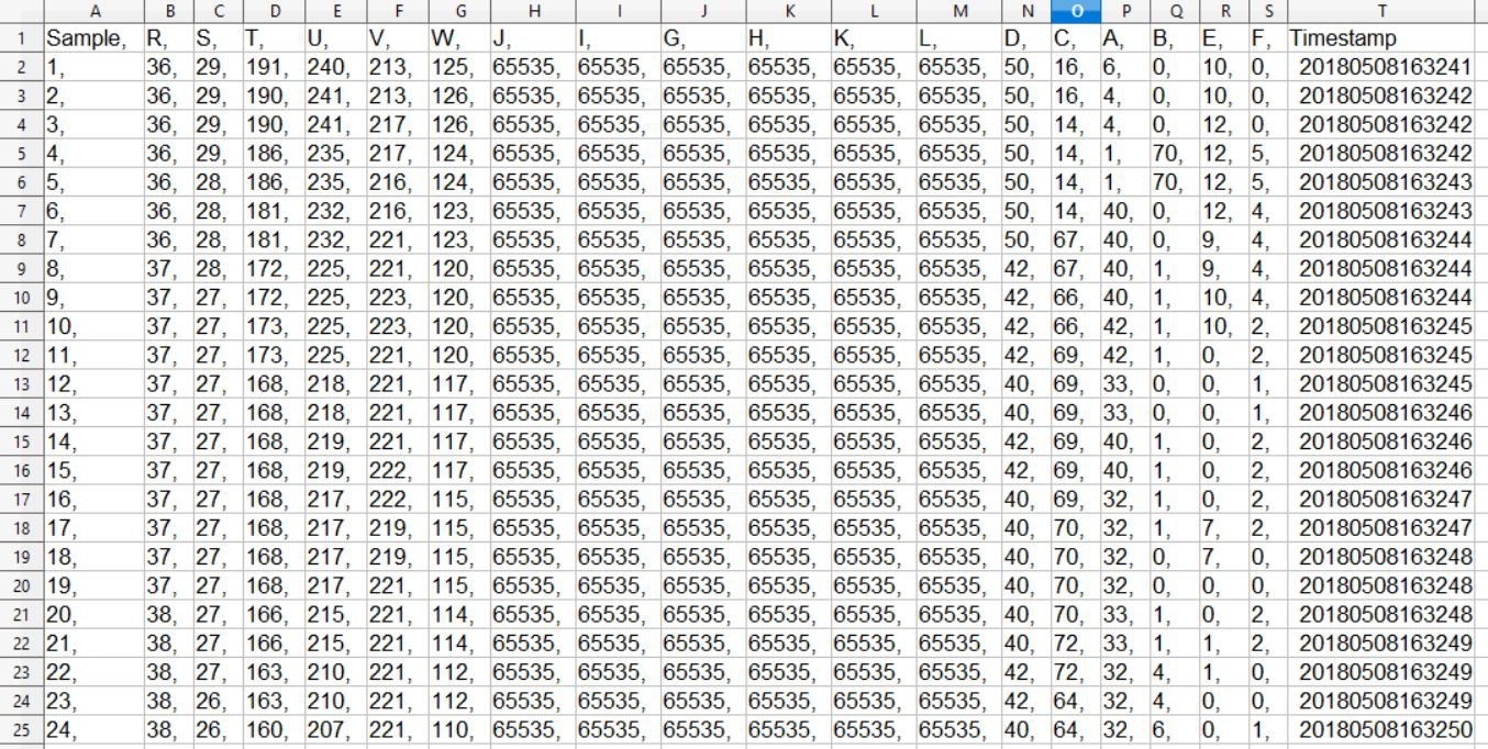
R-W channels are in the IR, A - F are in the blue and, unfortunately, I am missing G - K in the green/red.
Now the reference design is a curious thing, and there are some typos I am sure. (I am still waiting for AMS to respond to my few questions about the schematic, but so far, crickets...) One of which is the fact that the schematic shows AS72652 RST connected to AS72651 ADO. Huh? There is zero mention of this in the data sheet, the DemoBoard user guide, or the Hardware Design Application Note. Is it a typo, or is it necessary for getting proper performance from the AS72652? Well, I assumed the former in this design, but I am beginning to think the latter is correct. And, in fact, I finally checked the DemoBoard with a voltmeter and verified that AS72652 RST is not connected to the AS72651/3 RST pins as I had assumed for this design (silly me!) but is directly connected to AS72651 ADO! OK then. This must be correct!
So I redesigned the board to connect AS72651 ADO (pin 13) to AS72652 RST (pin 2) and I replaced the ADO PTH previously exposed on the board edge with another GND next to the I2C enable. This way, I can more easily jumper I2C_EN to GND for UART mode, which has so far turned out to be pretty darn useful with AMS's GUI.
I will start writing an Arduino sketch using I2C now that I have a partially functioning board and I am waiting for OSH park to fab the next revision. Overall, I am pleased with the progress and I hope that this can be the final revision for a fully functioning spectrometer. I doubt even in this case it will be the last, since I haven't tested the illumination leds (frequency, intensity, placement effects) nor put the calibration plate to work nor gotten a real sense of using the spectrometer, so future revisions are still likely. But I would at least like to start with a device functioning as intended. I think I am getting close....
*I wrote the bytes, maybe not every single last one of them but, yeah, basically, I wrote them...
Discussions
Become a Hackaday.io Member
Create an account to leave a comment. Already have an account? Log In.