 Owen Trueblood
Parts Ready for Assembly
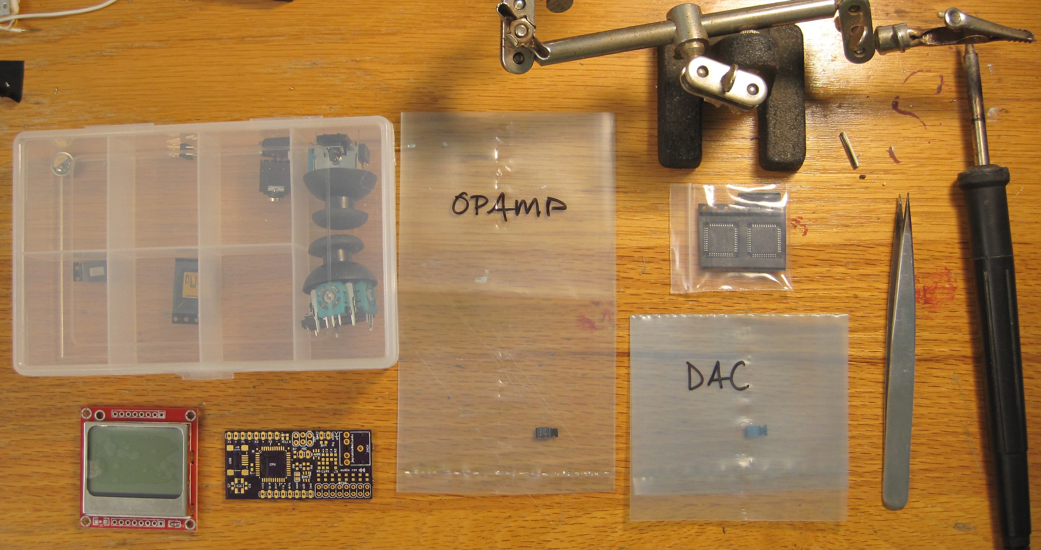
A month ago I designed a PCB for the first version of this project. I ignored the design that I had sketched out before and decided to make things up as I went along. So an Android phone is no longer involved and all of the audio processing happens on an AVR (for challenge). I did use an Atmega32U4 (found in a donated parts bin), so there is a little extra headroom in memory and I/O compared to the parts I usually use. A cheap Nokia 3310 screen is included to show the user interface. Two joysticks and eight buttons are provided for input (future updates will make the reasoning clear). A USB connection allows new firmware to be flashed via the Arduino Leonardo bootloader. Eventually it will also allow songs, samples, programs, and other tidbits to be saved or loaded to/from a PC.
Assembled
The board is assembled and I successfully flashed the Leonardo bootloader to the Atmega32U4. Unfortunately it was much more difficult to assemble the board than it should have been, because I mistakenly ordered most of my capacitors in the microscopic 0201 package instead of 0603 like I intended. The cause was my unfamiliarity with octopart.com. I filtered parts by 0603 and then did not double check that the results were actually 0603.
So I had to deal with parts so small that electostatic forces made them stick to my tweezers and iron. They were much smaller than even one 0603 pad. I got them all soldered successfully without too much fuss or frustration by nudging them into the right place and then holding them down from above with a needle while soldering. Another mistake that I made was overlooking that the USB connector and oscillator I chose have hidden pins on their bottoms. The USB pins were accessible from the side so it just took special care to get them soldered. But for the oscillator I had to do something extreme. I put a thin layer of solder on its connections and PCB pads, and then I balanced it on top of where it was to go and held a Bic lighter under that corner of the PCB for about a minute. Miraculously the solder reflowed and the oscillator was sucked into precisely the right position without any damage to the PCB. I will stow that technique for future use.
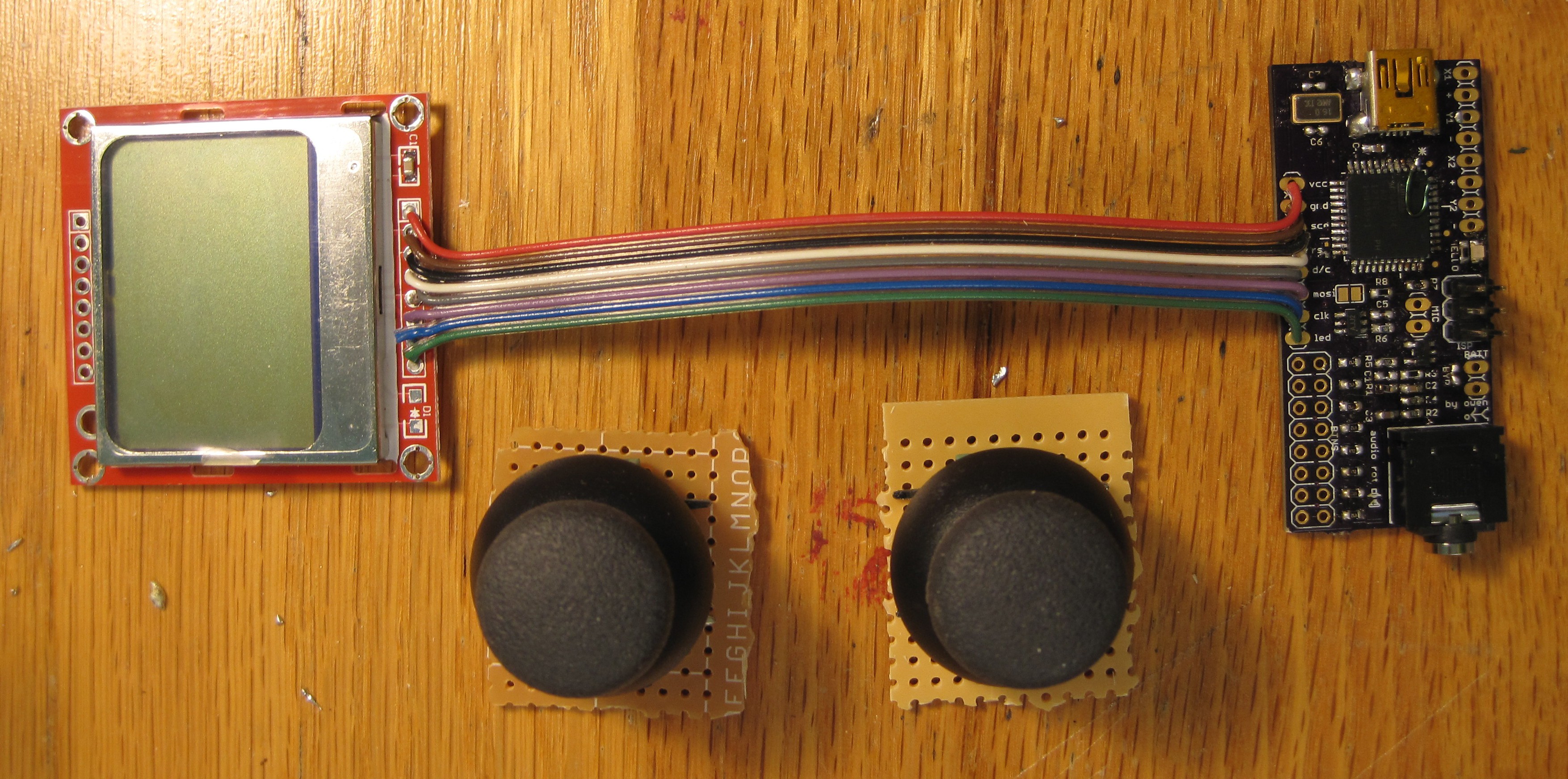
The joysticks were soldered to some roughly cut protoboard and the LCD was attached by a long ribbon cable. The joysticks are unsightly now but will look much better in the fully assembled instrument.
Discussions
Become a Hackaday.io Member
Create an account to leave a comment. Already have an account? Log In.