 Yann Guidon / YGDES
PLEASE tell me that this system already exits in the wild (or has existed) because it makes me feel uncomfortable to reinvent an ancient technology...
Borrowing ideas from ECL (non-saturated transistor logic) and from the single-relay flip-flop (using internal hysteresis), let's now play with non-saturated relay coils :-)
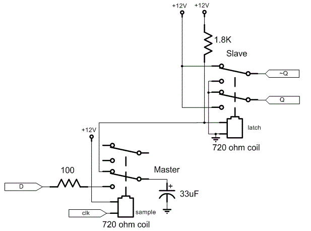 Relays have hysteresis. This is used by the flip-flop of the register set (see the principle, above, from http://relaysbc.sourceforge.net/circuits.html). But this could also be used for the logic, for these great reasons:
- Faster switching because less voltage difference
- more controlled average consumption
- no freewheel diode
- less current in the signals, increasing fanout
Let's simply start with the flip-flop and characterise the relay, to compute the right resistors/supply voltage.
I took 10 RES15 from their box and measured the following:
| # | coil (Ω) |
ON (V) |
ON (mA) |
OFF (V) |
OFF (mA) |
| 1 | 38.4 | 1.83 | 48.5 | 1.15 | 30 |
| 2 | 38.2 | 1.92 | 50 | 1.06 | 27.6 |
| 3 | 38.9 | 2.05 | 50.4 | 1.05 | 26 |
| 4 | 36.9 | 2 | 52 | 1.2 | 31 |
| 5 | 38.2 | 2.05 | 52 | 1.18 | 30 |
| 6 | 37.8 | 2.30 | 59 | 1.43 | 36 |
| 7 | 37.4 | 2.26 | 59 | 1.27 | 33 |
| 8 | 37.6 | 1.81 | 46.8 | 1.30 | 33.6 |
| 9 | 37.3 | 1.82 | 47.5 | 1.20 | 31.2 |
| 10 | 36.7 | 1.77 | 46.8 | 1.12 | 29.6 |
| avg. | 37.7 | 1.98 | 51.2 | 1.19 | 30.8 |
(note: the voltages might be slightly exagerated because the ampmeter was in series with the PSU, but the current seems to be the most important and stable value. Mechanical wear and temperature might also affect these values)..
The mid-range seems to be
- (51.2+30.8)/2 = 41mA
- (1.98+1.19)/2 = 1.58V
MinVon=1.77V, 0.19mV margin
MaxVoff=1.43V, 0.15mV margin
The deviation of the resistance is quite low, compared to the triggering values. 5% resistors will work...
What is the highest supply voltage that a 1/4W pull-up resistor can stand ?
U=P/I = 0.25W/0.041 = 6.1V (to be added to the 1.58V average).
With a 5V power supply for a latch, the resistor will dissipate 0.041*(5-1.58)=0.14W
That resistor will be R=U/I= 83Ω
This is close to the standard value 82Ω, but what supply voltage is required for a lower, 50Ω resistor ?
U=R×I = (50+37.7)*.041= 3.6V
The voltage swing now must considered:
- MaxVon=2.3V, margin: 0.72V
- MaxIon=59mA, margin: 18mA
- MinVoff=1.06, margin: 0.52V
- MinIoff=26mA, margin=15mA
A relay must pulse about 20mA to change the state of the slave coil. The system is more sensitive so the wasted energy in the bias resistor is compensated by the lower switched current (20mA instead of 60mA) which increases the fanout ! (going from barely 2 to 100/20=5 coils).
My stock has a quantity of 91Ω and 47Ω resistors.
- (47+37.7)*.041= 3.47V
- (91+37.7)*.041= 5.27V
These values are "close enough" to the standard 3.3V and 5V commonly found in power supplies, with a little offset (0.2V or 0.3V), which can be adjusted by a pot in several types of PSU.
The best choice seems to be a 3.5V supply. Not just because less power is lost in the pull-up resistor but more importantly because it is closer to 1.58×2=3.16V so a resistor tied to 0V or 3.5V will have roughly the same perturbation current.
OK now it gets fun: I just found a box of 1K 39Ω resistors. Which is, by coincidence, very close to the coil's resistance ! Calculations will become very simple :-)
At 39Ω and 41mA, the voltage is 3.15V.
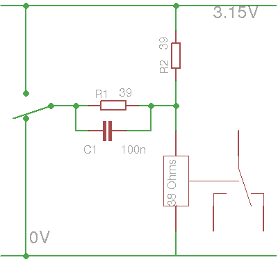
- When the left-hand switch is open, there is a 41mA current flowing through the coil. The previous state is preserved.
- When the switch is connected to 0V, the capacitor C1 will act as a short to 0V and both R2 and the coil's reverse surge will try to charge it. However there is a parallel resistor R1 of same value that will 1) discharge C1 (during times of bounces) and 2) keep the coil's voltage low.
- When the switch is connected to +3.15V, the same will happen but with reversed polarity.
Increasing C1 will help increase the value of R1 (and increase fanout). But with R1=R2=Rcoil, we have Vcoil = 1/3 or 2/3 Vp, or 1.05V and 2.10V. The capacitor is required to give the "extra kick" for the relays that trigger beyond these limits.
The total current, when R1 is connected to 0 or 3.15, is: 3.15/(39+(39/2))=53mA. Since Rcoil=R2, the current in R1 is half the total current, or 53mA/2=26mA. OK that's not the expected 20mA but we still have a fanout of 100/26=4 relays. Good !
The value of C1 is arbitrary and should be tested, for example at high frequency, since I have tested the relays near DC, with very slow ramps, and there could be some magnetic remanence.
Now, I haven't solved the problem of the XOR, and some AND situations, where both sides of the coil are switched.
Discussions
Become a Hackaday.io Member
Create an account to leave a comment. Already have an account? Log In.
Aging and testing endurance: Weibull analysis may spark your interest:
http://www.dtic.mil/dtic/tr/fulltext/u2/a143100.pdf
Are you sure? yes | no
I'll have a look, thanks again ! :-)
Are you sure? yes | no
Interesting... so the theory is that by keeping these coils partially-energized, it'll be that much quicker to switch on/off...?
This seems *exactly* opposite of what I'd've expected... Granted, my experience was with solenoids with plungers, rather'n relays, and I didn't really characterize them to a great-extent.
My experience was that faster-switching occurred when the voltage-difference from off-to-on was increased. Having a hard time phrasing this. But giving a smooth/slowly-ramped input-voltage, sometimes a solenoid wouldn't even engage when ramping up to the *full*/rated voltage. (and all it took was tiny factors, like a bit of vibration in the system to vary when it would switch). And, likewise, it would hold at a much lower voltage than rated, if already in that position. I figure, though, this was mostly to do with overcoming static-friction of the plunger via increased acceleration/jerk. Though, in the release-case, there's also the factor that the magnet is *touching* the plunger, no air-gap... OTOH, without a plunger... who knows. And reed-relays? Hmm...
It'll be interesting to see this come together.
Are you sure? yes | no
Hi !
No, the theory is not that it will switch faster, though it might because the swing is smaller, but this has to be measured.
And the RES15 is a kind of reed relay. Get yourself some :-D No idea how many remain though, I might have made a dent inside the stock but it seems to recover.
http://www.ebay.com/itm/351723476566
Are you sure? yes | no
Oh OK OK, it's not a reed relay :-D
https://hackaday.io/project/10889/gallery#759cd569aac813b3cbe14857bad20dca
which might explain its performance...
Are you sure? yes | no
Hah, I shoulda looked on the date of this entry ;) Lots of logs of its "coming together" thereafter.
Are you sure? yes | no
Major brain-fart... can't comprehend right now. And thought for sure this was a new log-entry for the relay-switching-timing test-circuit you've recently started.
Are you sure? yes | no
I'm weaving a web of logs to slowly create elaborated systems, sorry if I lost you :-D
Are you sure? yes | no
Well, that;s another $36 I won't have for retirement...
I couldn't help myself - I mean, you posted a link and everything...
Thanks!
Are you sure? yes | no
You'll thank me later :-D
Meanwhile, look at my analysis and experiments, that might save you some time :-)
Are you sure? yes | no
Solid silver contacts, it says. That could mean a few different alloys, each suited to different things:
http://www.te.com/commerce/DocumentDelivery/DDEController?Action=srchrtrv&DocNm=13C3236_AppNote&DocType=CS&DocLang=EN
But I think any of them would probably be OK for a relay/nixie clock, which is what I've been thinking. Relay ring counters.
Are you sure? yes | no
About the silver thing, I have no idea.
However I have measured that the coil voltage is significantly lower than the advertised one: average 2V instead of 2.8V (probably due to margin, variations, temperature etc.)
It is meant to switch 150V so it could probably drive nixie tubes. The limit is the spacing between the contacts, very close and they could arc.
Care to share your relay ring counter topology ? :-)
Are you sure? yes | no
The 2.8 may be a "must make" spec, and they're allowed to pull in anywhere below that. There should also be a "must release" spec - maybe they both have to be measured at this point.
Oh, the relay ring counter? Haven't designed it yet ;-)
Johnson counters plus decoders are done to death; there must be a simpler way, don't you think?
Are you sure? yes | no
You're asking *me* that ? :-D
For #Yet Another (Discrete) Clock I do the Johnson ring but no decoding :-P Direct drive !
Are you sure? yes | no
So, the vague idea is that since the relays have a built-in hysteresis, you can make a 2-terminal latch that pulls in above Vx, but doesn't release again until it drops below Vy (Vx >> Vy). 2-terminal latches (emulated Shockley diodes) are used here to make a ring counter:
http://www.dos4ever.com/ring/ring.html#shockley
I'm thinking a relay and a resistor could make an "electromechanical emulated Shockley diode"
Now, I need to get some sleep; by the morning, the idea should come...
Are you sure? yes | no
OMG there are so many ideas for #Clockwork germanium !
Are you sure? yes | no
Ted, it's not nice to give me so many ideas.
Are you sure? yes | no
Just think were we'd be if it were thirty years ago: no Internet for inspiration and no ebay for junk parts. We'd all still be hanging around brick-and-mortar surplus stores and going to the library.
Are you sure? yes | no
I don't regret my childhood. I just wish it wasn't so long :-D
Are you sure? yes | no
Sliding mode control: you'll find a good intro here: http://www.uni-obuda.hu/journal/Szell_Korondi_49.pdf
Your relay solenoid dissipates in the order of 0.1W. This isn't much (a standard 14V vehicle relay dissipates about 2W which brings the temperature up to above 100 °C at 25 °C amb. 10 Ohm (non adjustable!) in series decreases the temperature impact on the current. In the (extreme) case of Ub=100V, and Rcomp = 2kOhm the effect is negligeable ;-)
Are you sure? yes | no
I don't see the relevance of sliding mode control with the small RES15 relays :-D
The idea of an adjustable resistor (added to the biasing 39 Ohms of the latches) was to compensate for the variance of the coils and enhance the immunity to drift compared to other neighbour relays.
Are you sure? yes | no
Sliding mode (switching relays between states as fast as possible to avoid chatter) is a technique to blend two otherwise instable control modes to a new one that's stable. The connection lies in "fast", and in "stable". With "stable" we get into a different domain here, because in digital circuit stable often means "avoiding race conditions", the hazards of relying on uncontrolled timing. In the end, this is why relays fell out of favor for all but the least complex circuits (e.g. without memory and feedback loops).
Tuning relays with an adjustable resistor might help to get the circuit running at one point in time, but unless you design the digital circuit to be very tolerant against race conditions, re-tuning will be an important task to keep the circuit operational (not to mention reliable) as contacts and mechanics age (or the ambient temperature changes if the circuit is very sensitive to "race") .
Are you sure? yes | no
Aging will be a concern....
I have broken 2 relays by wiring them incorrectly (and making them oscillate extremely fast).
I need to figure out a system to test their endurance.
Are you sure? yes | no
Interesting - this has the potential to bring sliding mode control back to its origins ;-)Did you take into account the temperature coefficient of the solenoid?
Are you sure? yes | no
Hi Thomas !
What is "sliding mode control" ?
The tempco, hmmm.... there is some drift, maybe 10% so (like many "oldies") the system must be developped with "some margin" and measurements must be done after 20 minutes :-P
Yes, the coil is energised most of the time, which is good AND bad, it depends what you're looking for and what compromise you can accept.
Anyway I'll test the coils "cold", hoping they will not deviate even more when "hot"... In particular, the hysteresis "latches" (one relay can store one bit) are the most sensitive parts. Maybe I need to add 10 Ohms adjustable resistors in series ?....
Are you sure? yes | no