 Yann Guidon / YGDES
The system is getting a bit more complex... but bear with me ;-)
A previous log, Fanout and multi-rails power supply, came to the conclusion that 2 voltages were needed to kep the liaison capacitors from being polarised in reverse.
What came to my mind is this:
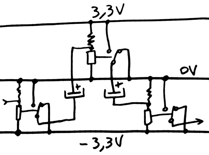
The logic output of one relay goest to a relay in the opposite rail. This way, the capacitors are always correctly biased. Alternating power rails is a method used in the first ECL circuits...
But this creates more new problems, that I will spare you (and leave as an exercise to the reader if you are versed in the art). Drawing the above circuit, it appeared that I was blindly repeating what I already knew, yet forgetting that the new and different context has more flexibility.
Unlike transistors with only 3 pins, the relay has 5 and it's possible to "shift" the voltage of the switch :-)
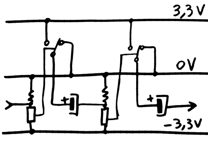
Then, the system is greatly simplified, there is no question about controling relays on both rails at the same time with a unique signal.
The main rail (0/-3.3V, but it could be reversed) can sustain most of the load (a constant 40mA/relay), while the positive side (0/+3.3V) must only sustain spikes (the average current is lower but it requires more decoupling).
Is is already known that the "latch" coils require a separate 3.3V power supply to isolate them from the spikes of other activities. Long coil strings also require another PSU at about 20V. So it's not really an inconvenience to have 4 instead of 3 PSU...
But wait!
Since the bias resistor has the same value as the coil, what keeps us from replacing it with another coil ?
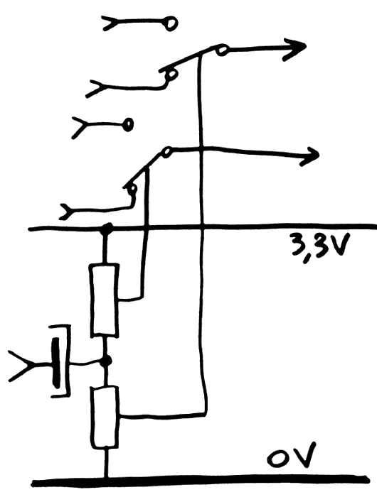
Yes, we get a DPDT with no increase in power consumption. Just make sure that there is no path that allows short circuits because the relays don't switch exactly at the same time.
This is particularly interesting for the carry logic, which is still being studied...
But this is not the end yet !
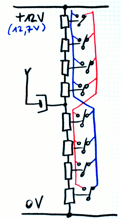
I mentioned that there is a need for a 20V PSU, to power the long strings of 8 relays with high fanout. The calculation is simple : 8 relays require 2V each to turn on, that's 16V, plus a suitable resistor to tune the string to at least 60mA. 18V won't do and I have some 20V PSU around.
But the above DPDT circuit can be easily extended into a 8-pole pseudo-relay with prebias, using a bit more than 12V ! The bias voltage is approx 1.58V, or 12.64V for 8 relays. The working point can be adjusted on classic open-frame blocks.
The drawback is the higher quiescent current, but it will remain pretty stable during operation, preventing load-dependent fluctuations and heating.
Another auxiliary 12V PSU is required to polarise the liaison capacitor.
But the same 12/13V that powers the long strings can be used directly by the DC/DC to generate 3.3V, saving some complexity as well.
(note: the liaison capacitor should probably be increased from 100µF to 470µF because there are more coils to drive, but the increase of voltage might compensate as well. Anyway, more capacitance can increase the working voltage margin, when using relays with mixed characteristics)
Do you see the crossing in the middle ?
When there is a low-going pulse, the bottom relays get de-energised while the top relays "stick". And vice-versa. If all the data must be coherent, then the polarity must be exchanged somewhere.
The good news : it can simplify the wiring and control of the register set MUX8s.
The bad news : the power consumption just increased. Though probably not by much since some relays would draw >60mA anyway. But at least the heating is totally balanced and not load-dependent, which adds a bit of reliability.
Another bad news is that I must check ALL the relays for Von/Voff before wiring, which makes the #ReTest-RPi project more important.
You know what would be even better ? That the new circuit gets actually tested on the bench, because I've had enough bad surprises already :-D
Discussions
Become a Hackaday.io Member
Create an account to leave a comment. Already have an account? Log In.