Shortly after I started printing there were developments in auto calibration/levelling/tramming. Probing with the version of Marlin I had was in its infancy so I didn’t get very far.
I had always levelled the bed using thin paper and pre-set positions at the base of each tower. I had designed the hall effect endstops to be slightly adjustable so it was fairly quick and painless to calibrate. It would normally take about 5 minutes to get an acceptable calibration.
When I upgraded the printer controller in 2016, I thought I would give Z probing another go. Around the same time, I replaced the perfectly flat glass heated bed plate with an aluminium plate laminated with PEI sheet. The new heated bed was very flat but not as perfect as the glass. I was very interested in using grid-mesh bed levelling to try and compensate for the irregularities.
I purchased a small infrared gate sensor and, using a pen spring and 2.5mm rod, designed a compact Z probe. I chose the infrared sensor in the hope that it would be more repeatable. The spring was held in a little channel and secured with a terminal screw from a salvaged mains terminal strip. I printed a tiny little flag to go on top of the shaft which would pass through the infrared sensor.
I decided that automatic probe retraction was not really necessary considering tramming would not be done very often. The added complexity of a probe retract mechanism was overkill for me. The probe could be engaged by lifting it slightly and pushing it inwards. To disengage, it could be lifted then pulled outwards.
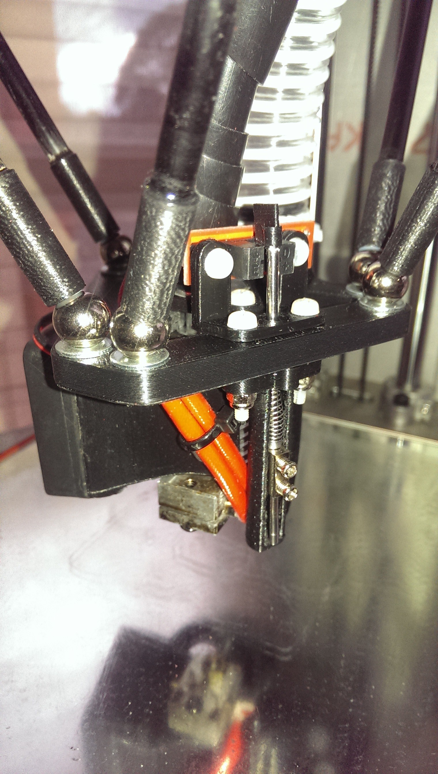
Probe retracted
The probe worked very well mechanically. Unfortunately, the final tramming result did not go very well. Any variation in the delta mechanics can cause the end effector to become slightly out of parallel with the heated bed. The variations were caused by slight misalignments of the magnetic balls, imperfections in the printer frame and the Bowden tube exerting a twisting force on the end effector. As the probe was offset from the nozzle about 25mm, this meant that the trigger point could vary depending on where the end effector was on the bed. It wasn’t much but was enough to cause the nozzle to drag on one area of the bed and remain airborne in another area.
My solution to this was to use the nozzle itself as the Z probe. This would eliminate the offset and hopefully cancel out any mechanical imperfections or twisting of the end effector.
I designed many prototypes of a hinged extruder that would tilt slightly when pressed against the bed. I first utilised the existing infrared gate sensor but later moved on to a simple microswitch. I also had to consider how to fit the cooling fans and cable connections within a compact footprint. It is hard to see the mechanism in photos so here are some CAD snips:
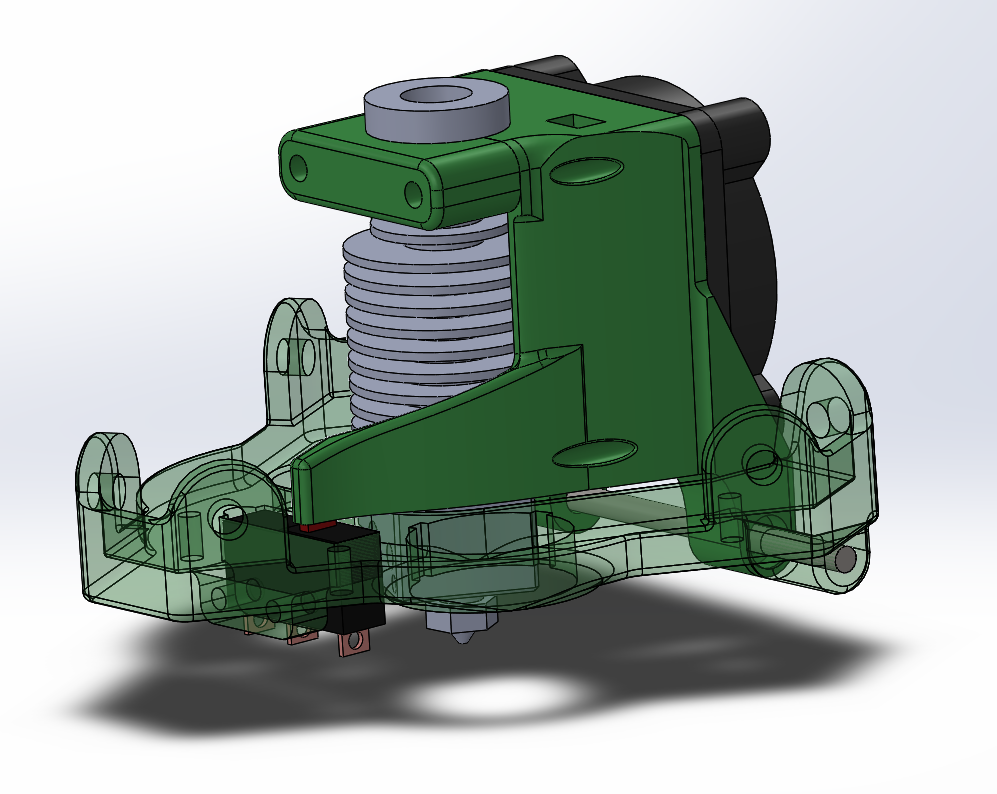
Hinged extruder and microswitch
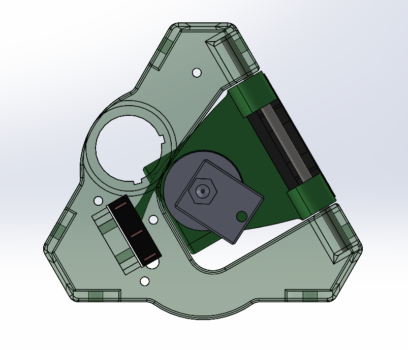
View from underneath
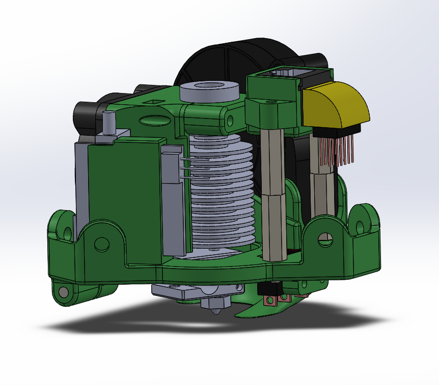
Final assembly
Z probing now works very well and is reasonably repeatable.
I run the following G-code assigned to a custom menu item:
M190S60; Set bed temp to 60 degrees C
G32; Do endstop offset and delta radius calibration
M500; Save settings
G31; Do delta grid probes across the bed
M374; Save grid to SD card
M500; Save settings
G28; Do home
G0Z5F6000; Move nozzle 5mm above expected bed hight
G38.3Z-10; Slowly lower nozzle to detect bed and stop
G91; Switch to relative movements
G0Z0.7; Raise nozzle to perfect Z height - where microswitch has released plus a little extra
G90; Switch to absolute movements
M306Z0; Save Z height offset
M500; Save settings
G28; Do home
G0Z75F6000; Park just above the middle of the bed
M190S0; Turn off the heated bed
After this routine, the printer is in “tram”.
Discussions
Become a Hackaday.io Member
Create an account to leave a comment. Already have an account? Log In.