 Craig Watson
In order to validate the concept, I bought a pressure sensor and two solenoid valves (see bottom of this post for details). The pressure sensor is a fancy Honeywell model that includes electronics to amplify the signal, and transmit the measured pressure over SPI. This makes it super easy to use, as there are just a few wires to connect; no amplifier to design, not much to troubleshoot, and nothing to calibrate.
For the solenoid valves, as alluded to in the project description, I got one proportional valve and one non-proportional (i.e. open/close) valve. Proportional valves are necessary to smoothly increase the amount of air that is let in (since they can be opened anywhere from 0 to 100%), but I thought I could get away with a cheaper (35$ vs 70$) valve for the exhaust. Since the exhaust only opens every now and then to correct for overshoots and to release pressure when the setpoint is lowered below the current pressure, I thought a trade-off in precision might be ok.
So, once I had tested each part individually, making sure I could read pressure and control the valves with an ESP8266 I had on hand, I dug into my collection of tubing and fittings to put together a first prototype:
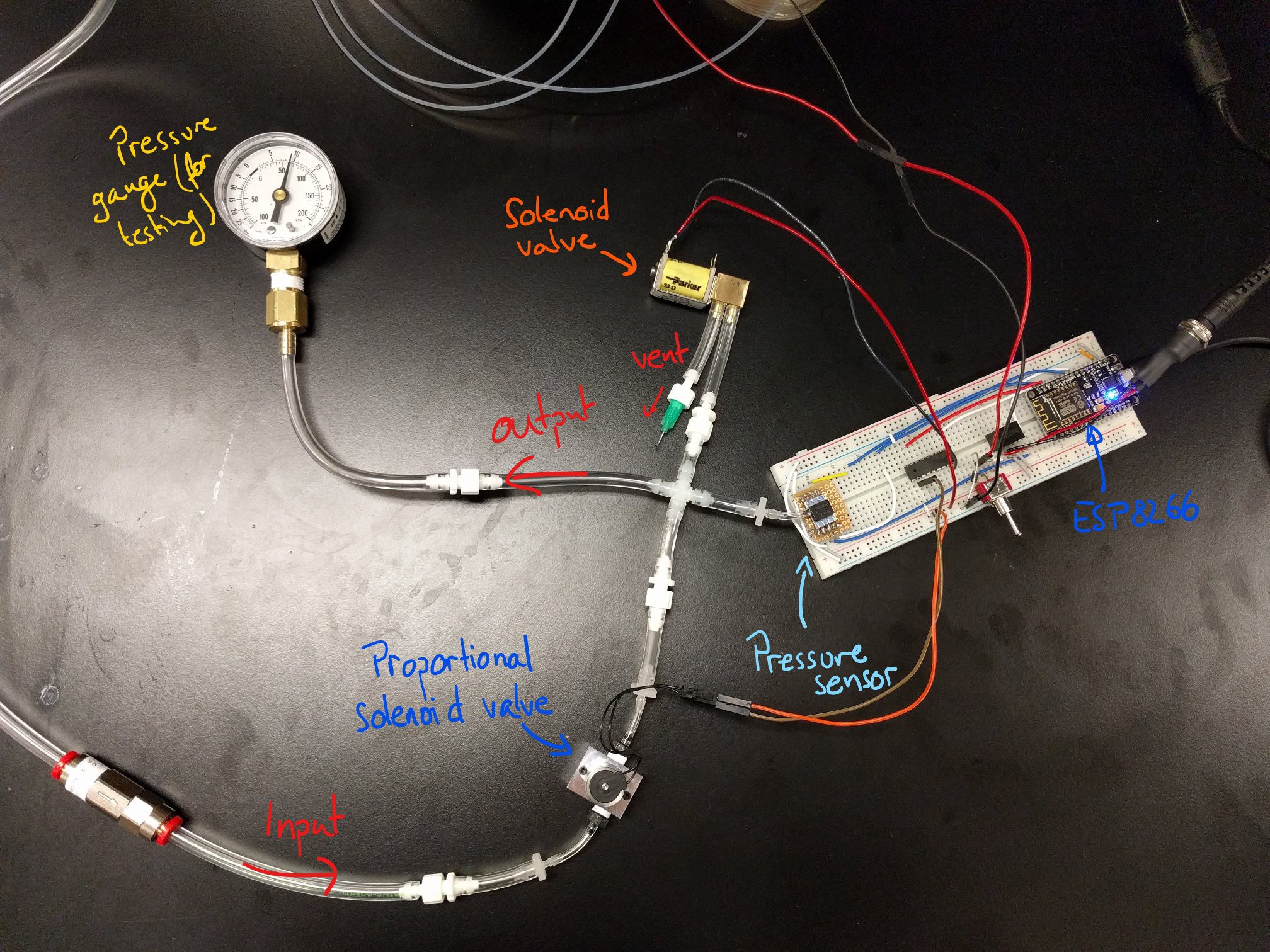
The pressure gauge here is for testing purposes; this is where you would plug in whatever you need pressurized. In my case, it will be a bunch of solenoid valves connected via small tubes to a microfluidic chip, with mostly-closed channels. Therefore, the sealed output here is actually quite close to my intended application, which will consume little to no air.
Out of frame is a 12V diaphragm pump, which provides the pressurized air (at up to ~25 psi = 1.7 bar). The switch sticking out of the breadboard, on the right, turns it on and off. A check valve placed between the pump and the inlet valve smooths out the supply somewhat, and holds the pressure downstream even when the pump is turned off.
On the software side, I made use of the Arduino PID library. The output is clamped between -1 and +1. Positive values open the inlet valve (which is controlled by PWM, so analogWrite(0) closes the valve, analogWrite(512) opens it half-way, and so on).
For negative values, it is a little more tricky. The vent valve can be only fully closed or fully open, and it vents quite a lot of air every time it is open, even for just a few milliseconds (it takes ~25ms to open it and close it). So if the output of the PID controller is, say, -0.01, and we are just above the setpoint, I don't want to vent so much air that we drop to 50% of the setpoint. I am dealing with a non-linear, non-symmetric system so a simple PID controller won't work. My McGyvered solution was to set a threshold for opening the vent: if the output of the PID is below that threshold (arbitrarily set around -0.5), the vent valve is opened.
This did work to some extent, and rapid pressure deflation is easy to achieve; however, fine control is not so easy. Pressure will often swing wildly around the setpoint for a second or two before stabilizing, and there is no good way to reliably get close to the setpoint with this setup. I would welcome any suggestions to improve control of this sort of system, by the way.
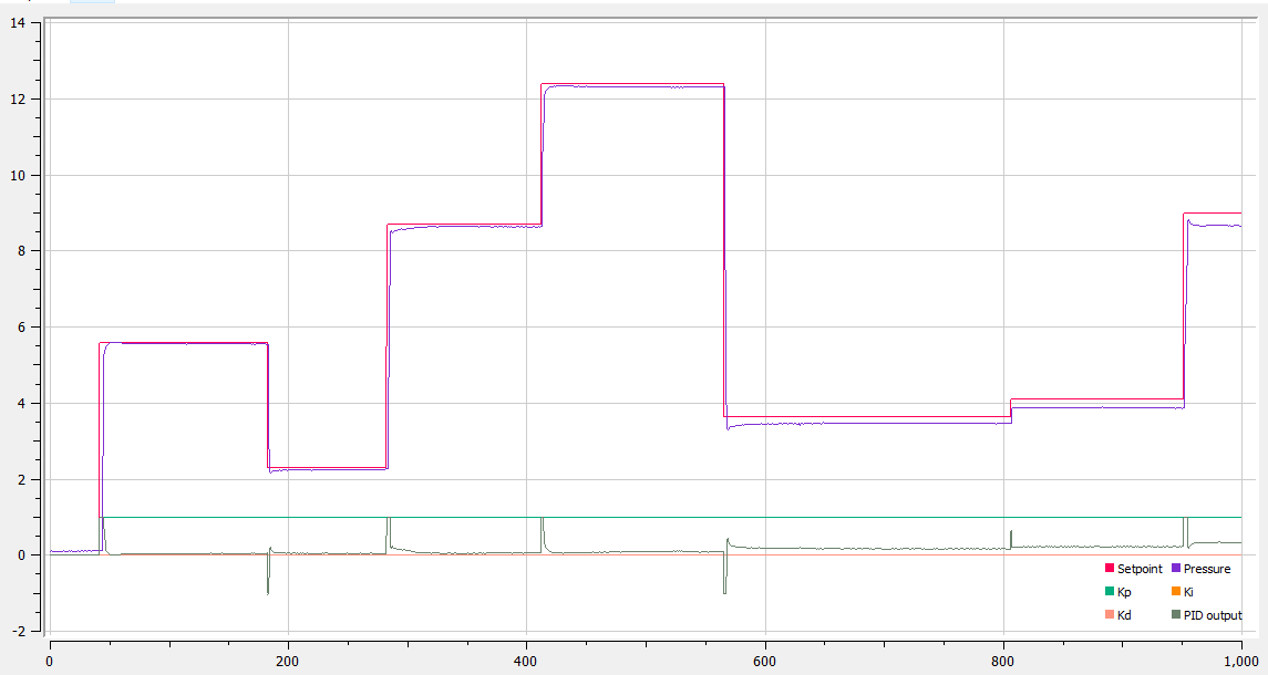
Below is an example of proportional-only control (i.e. Ki = Kd = 0), working out fairly well:
And an example of it working out slightly less well:
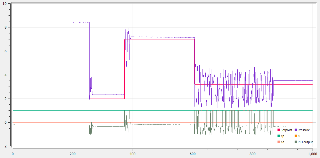
The problem is that even a short opening of the vent leads to a big drop in pressure, making fine adjustments difficult.
I was actually able to alleviate the issue somewhat by placing a very small restriction on the vent, which reduces the flow rate out of the vent and thus the pressure drop whenever the vent is opened. There are still considerable spikes though. I think a better handling of PID output (allowing both the inlet and the vent to be open at the same time, for example) could help even more.
Still, the easier solution is probably to place a proportional valve on the exhaust, which is the solution I have decided to go with for now. This increases the cost of the regulator by ~35$, but it should be much more robust, and easier to develop. I may come back to this simpler setup later, however.
Components used
For this prototype, I used:
- Parker VSO LowPro proportional valve (935-300050-000)
- Parker Series 11 normally-closed valve (991-000316-008)
- Honeywell HSC series pressure sensor (3.3V, SPI) (HSCMRNN030PDSA3)
- ESP8266 (later, an ESP32) dev board
- Recom R-78 voltage regulator (12V->5V)
- ULN2803 to power the valves
Discussions
Become a Hackaday.io Member
Create an account to leave a comment. Already have an account? Log In.
Awesome work! Absolutely a low cost solution. This should be the very beginning of this project: https://hackaday.io/project/27511-microfluidics-control-system
Nowadays, choose microfluidic pressure controller from the market is also a choice, like these
https://www.fluigenti.com/
https://www.precigenome.com/ufluidic-controller
Are you sure? yes | no