 Shervin Emami
RI knew the speed of light is extremely fast but I wasn't sure how fast my IR LED would reach full strength and how fast my sensor would show the full signal. If they're ultra fast (hundreds of thousands of times per second), then I could send a unique pulsed message and then decode the message, to be sure the signal came from my LED and not other signals, whereas if it's quite slow (a hundred times per second) then I wouldn't have enough time to send much of a coded signal for reliability unless if I made the device update very slowly (eg: 5 times per second, instead of 100 times per second that I'd much prefer).
So I borrowed my friend's Oscilloscope to see the behavior of the voltages moving very quickly and in very fine detail. I put together the simple IR emitter LED circuit shown below:
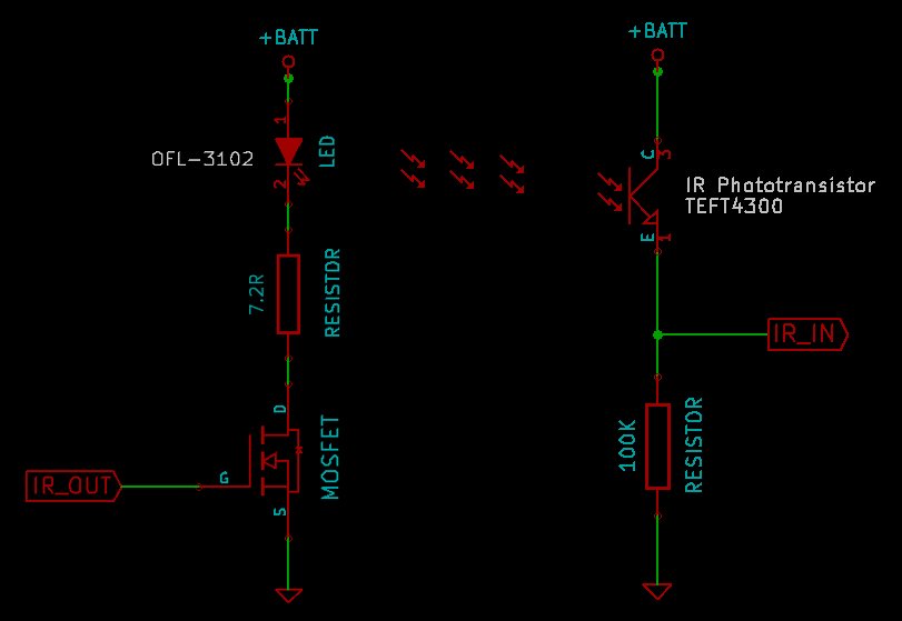
I connected IR_OUT to a GPIO pin on a 5V Arduino microcontroller, connected a 4.2V DC power source (equivalent to a fully charged LiPo battery) to +BATT, and connected IR_IN to the Oscilloscope. I placed the IR emitter LED and IR phototransistor next to each other, facing the same direction so that light from the emitter can reflect off an object and back into the receiver. Both the IR emitter LED and the IR phototransistor look like 3mm LEDs, and fit easily into common 0.1" spaced connectors. Since I wasn't sure whether I should place the IR LED and phototransistor in parallel or spaced a little apart and angled in slightly towards each other, I put them into an 8-pin 0.1" header socket and wired the connector up so I can easily plug the LED into different pins to see which one gives better response, as shown below:
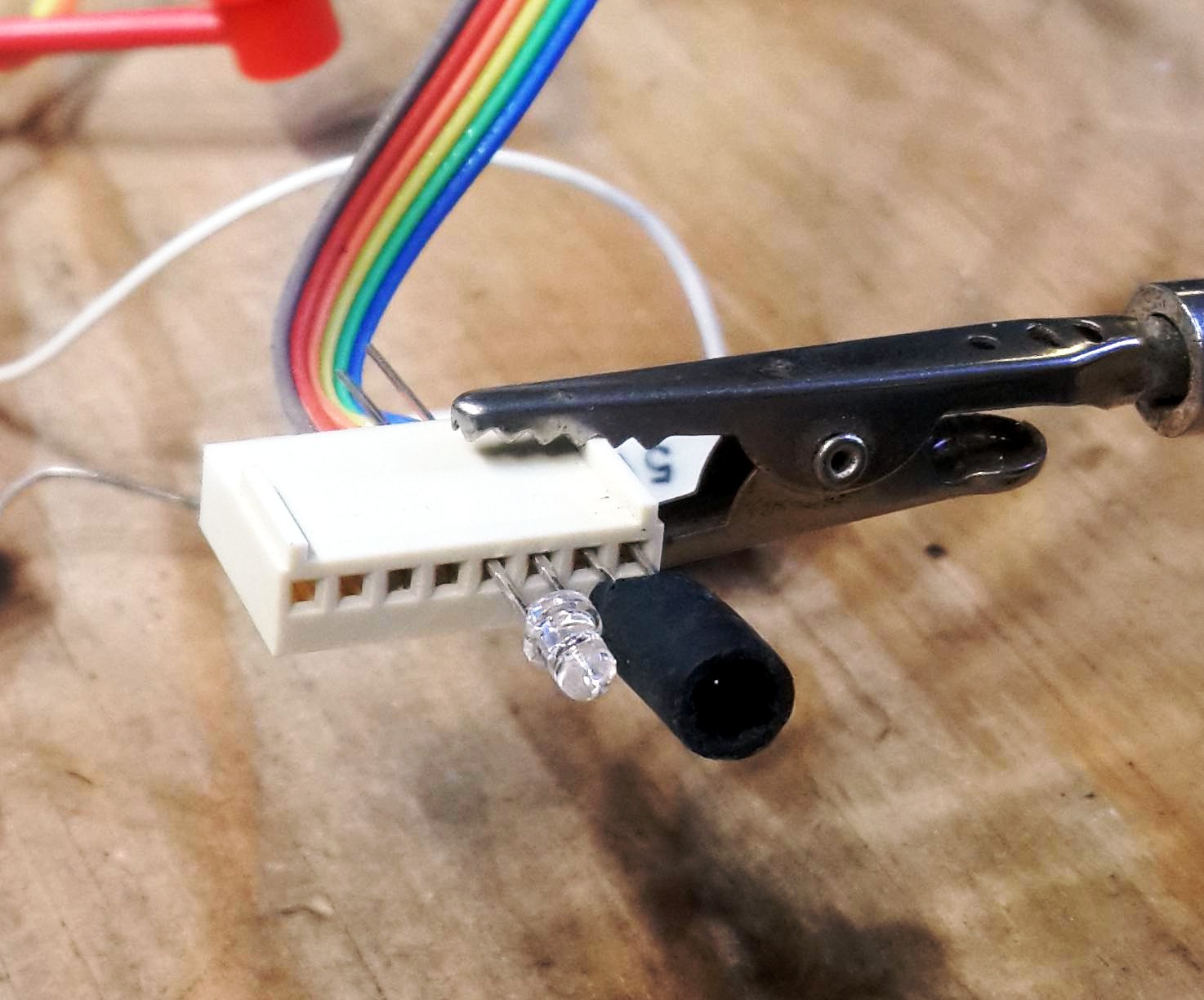
The clear LED is the IR emitter LED, and the black rubber tube next to it contains the IR phototransistor. The phototransistor actually looks the same as the LED but its black, and I put the black rubber tube around it so the receiver is more narrowly focused on the reflected beam from the emitter LED.
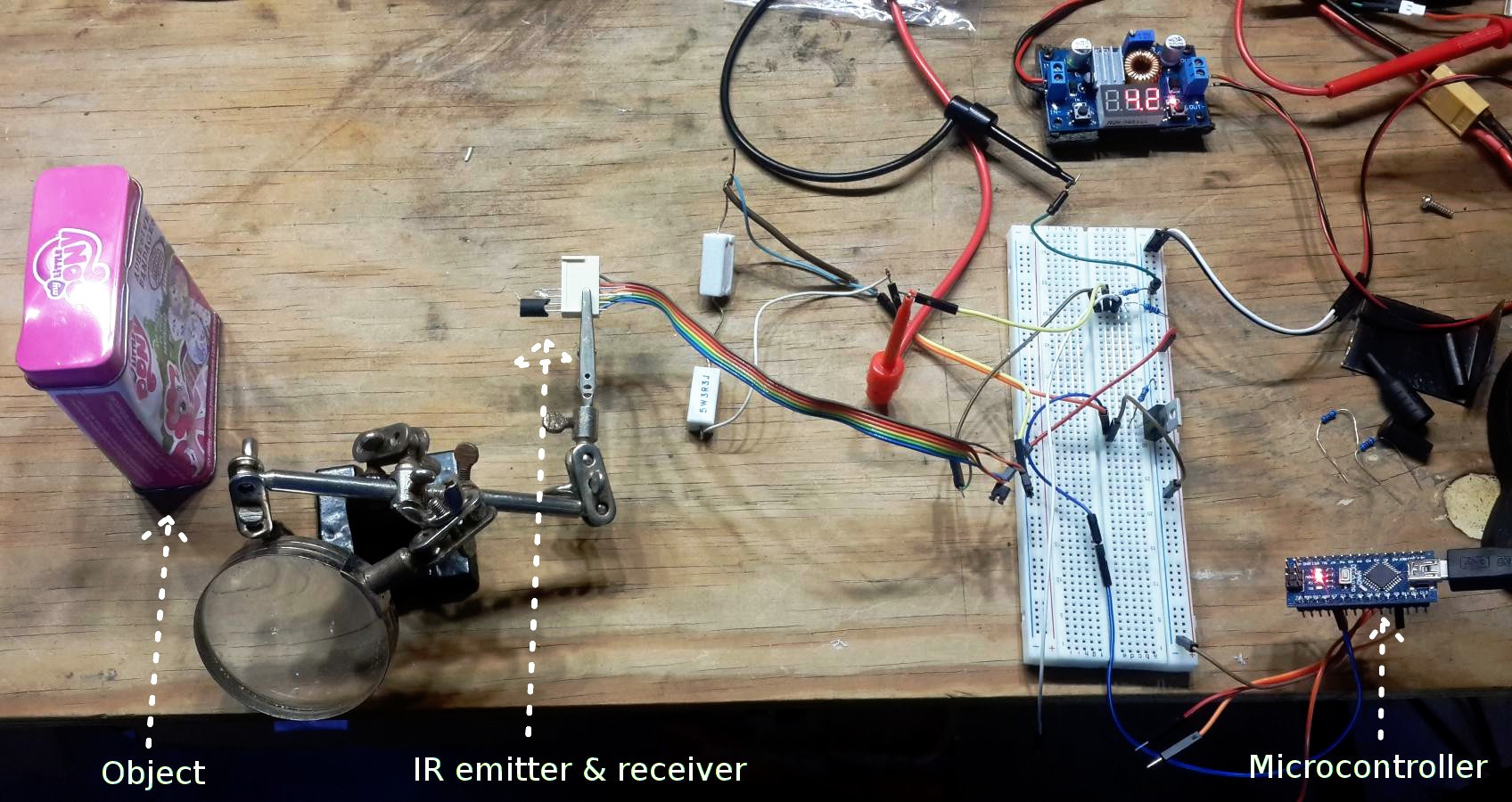
Then I put a glossy object to reflect the IR light back into the phototransistor, so I could measure the time between sending a pulse and receiving the pulse. Here is a photo of the setup:
Results of the timing test:
When looking at the results, I was quite surprised when I saw the the IR_IN voltage on the Oscilloscope, as shown below:
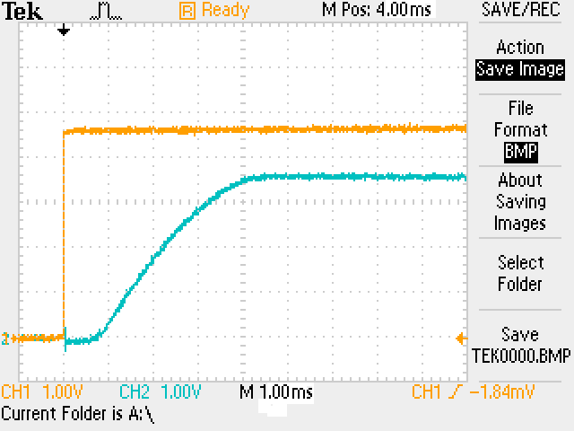
The Oscilloscope measurement of IR_IN shows that when I send an IR pulse, the IR phototransistor actually needs a fair amount of time to ramp up to the correct value! Each square block in that Oscilloscope plot is 1 millisecond (1ms) wide, so it takes around 4ms for that phototransistor to show the full signal! The Arduino analog port needs a default of 0.1ms to measure any voltage, so it means I need to leave the IR LED on for roughly 4.1ms to get the full signal! That's way too long of a duration to allow pushing an LED to its absolute current limits, so I will stick to driving the LED around its "continuous" current limit. For the OFL-3102, that's 50mA instead of the 200mA peak rating.
But the slow speed of the phototransistor also changes the way I need to write the software. If I simply turned the IR LED on and measured the analog signal straight away, I'd be getting the voltage just 0.1ms later and so I wouldn't see any signal! So I need to add several milliseconds of delay before measuring the analog voltage of the phototransistor.
I did some further experiments with the setup above, and noticed that the speed of the phototransistor is related to the resistor I put in series with it. If I use a 1 kOhm resistor instead of the 100 kOhm resistor, the response is much faster but it's also a much lower voltage swing, and so I wouldn't be able to get much detection range without it getting too much interference from electrical noise. I tried other values such as 10k, 20k and 40k, they behave quite similar to the 1k resistor. ie: several times faster response than with a 100k resistor but the signal is also several times weaker and so the measurement distance becomes just around 1 foot instead of 3 feet.
Anyway, it's definitely good to see the signal does in fact change based on distance of the object, and even objects 2 to 3 feet away can be detected :-) At roughly 3-4 feet away, the signal is only around 20% higher than when no object is there, so that's probably the limit of what this setup can achieve unless if I use more LEDs or higher current or more powerful LEDs or more focused LEDs. But I feel 2 to 3 feet is enough max range for now, so I'm happy with the results!
Discussions
Become a Hackaday.io Member
Create an account to leave a comment. Already have an account? Log In.