 Shervin Emami
I built the initial prototype, and got it working! It doesn't work as well as I hoped, there was a lot of crosstalk noise between the IR Emitter and IR Receiver even with the 2 black tubes separating them, but they were spaced VERY close to the each (just 2mm gap), so I added a bit more space between the IR Emitter and IR Receiver to reduce the crosstalk. But I still need to reduce the noise further if I want it to have longer range. Currently it has about 60cm range, but any further than 60cm ends up looking like noise, because of the crosstalk noise. So tomorrow I'll try covering the back of the IR Emitter and Receivers, because I'm guessing that's where a lot of the crosstalk is happening.
Anyway, here is a photo of the working initial prototype, that currently has about 60cm range!
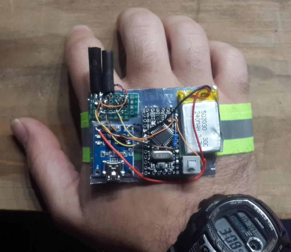
- Top-left section: Custom electronics I painfully made using point-to-point wiring on a piece of stripboard.
- Bottom-left section: USB battery charger.
- Middle section: Microcontroller.
- Top-right section: LiPo battery.
- Bottom-right section: On/Off button.
Note that while I initially used a 100K Ohm resistor in series with the IR receiver, I added an extra 200K Ohm through-hole resistor in parallel to it but very close to the microcontroller analog input pin instead of being very close to the IR receiver, to reduce the effect of electrical noise, since I noticed that the wires between the microcontroller to the stripboard picked up a bit of electrical noise (probably from the vibration motor).
Also note that I used a fairly large On/Off button for easy testing, but once I put the electronics into a 3D printed enclosure, a much smaller switch could be used. Initially I expected to use a momentary push-button instead of a latching On/Off switch, but for now I'm using an On/Off switch for easier prototyping and because the Arduino bootloader is currently taking several seconds of waiting before it boots up my code.
UPDATE on 10th Oct 2016:
Here is a close-up photo of the custom SMD electronics I built on a generic veroboard / stripboard PCB. As I mentioned, it is ugly, but it works for now until I get a proper SMD PCB made up!
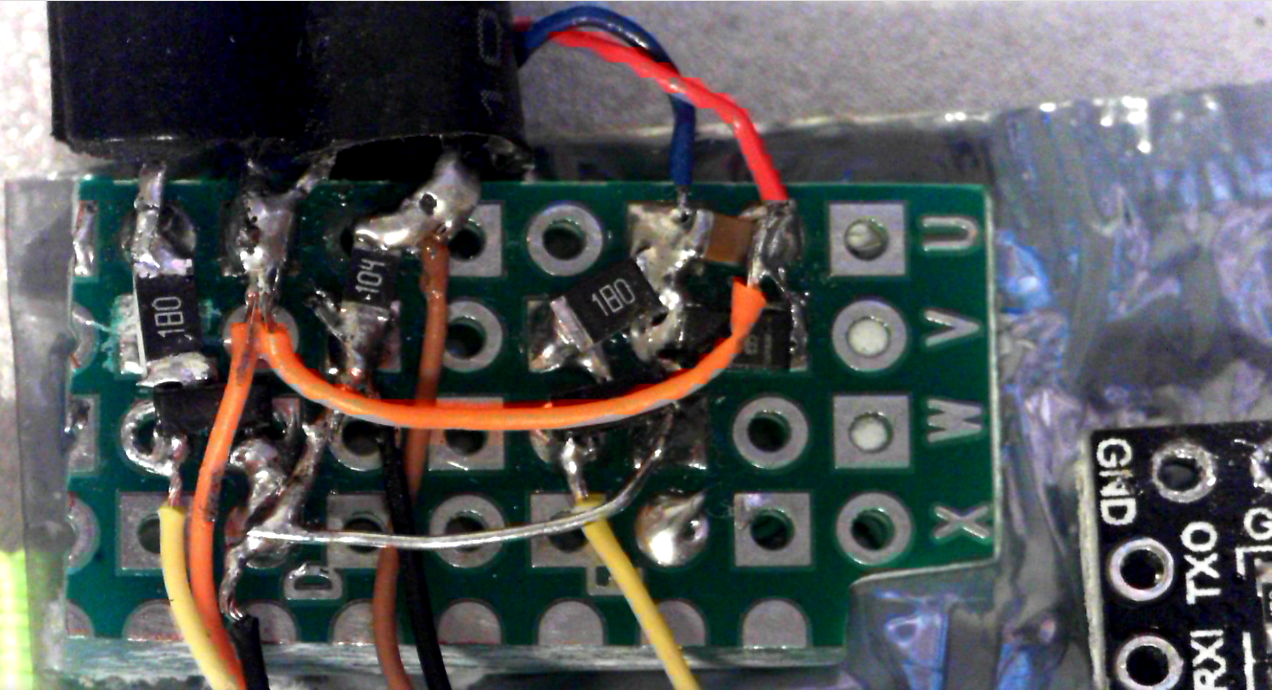
The 2 black tubes on the top-left are the IR emitter and IR receiver. The vibration motor is just beneath them, so that the user will feel the vibration at a similar location on their hand as the sensor is, probably making it a bit easier to map in their brain than if the vibrator was placed a few centimetres away from the sensor. The 2 black ires are ground (one black wire is only connected on one side, and is wrapped around the brown signal wire as a basic form of electrical noise reduction). The 2 yellow wires are GPIO output signals from the microcontroller to turn on the 2 MOSFETS (barely visible under the wires in the photo!). The orange wires and red wires are all connected directly to the Battery positive.
Discussions
Become a Hackaday.io Member
Create an account to leave a comment. Already have an account? Log In.