 nerd.king
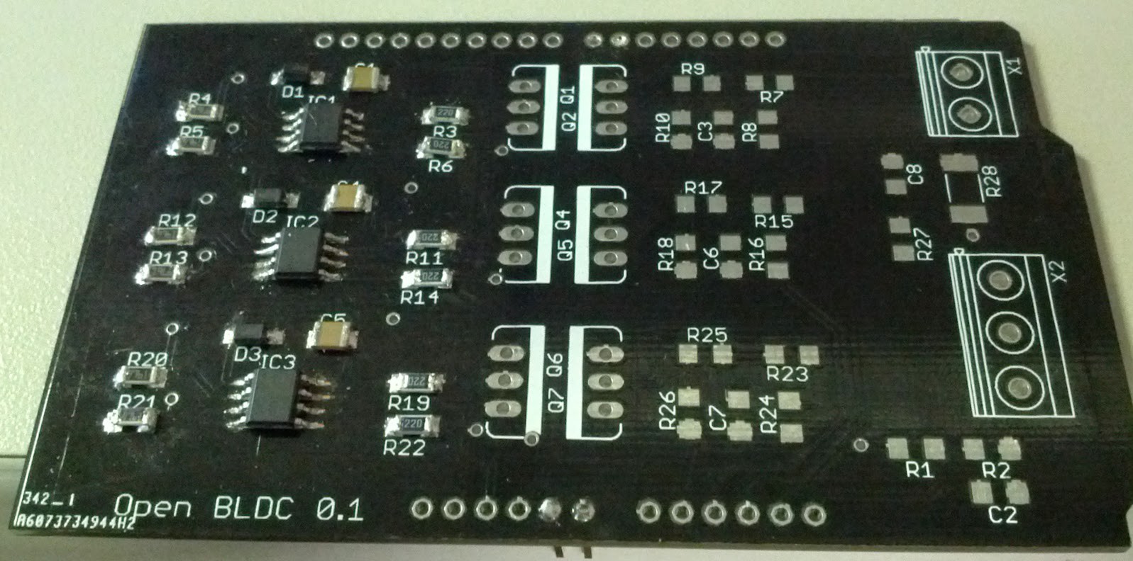
So I ran into multiple issue soldering up the perf board and decided to go with the PCB. It took a couple of times to get the board this clean. Currently the HI/LO drivers are powered by 5V from the arduino. After testing with 5V power the driver and toggle each input none of the outputs worked correctly. I ohmed out all the connections and everything looks good so I figured I should read over the driver datasheet again. And much to my happiness and chagrin, Vcc need to be greater than 10V. So this shouldn't be a horrible mistake and I think I can use the 24V that is going to the FETs to power the chips. I will update again after I am able to run addition tests.
Discussions
Become a Hackaday.io Member
Create an account to leave a comment. Already have an account? Log In.