 Brian Gilbert
While thinking about how my project could fit into the robotics module competition, there weren't a whole lot of options available besides the auto-leveling and tilting mechanism. This also has the benefit of being one of the lower-cost portions of the build and potentially requiring fewer tools as long as I can find a way to use off-the-shelf parts.
First, I had to figure out what to use. I considered PVC, but I already knew going in that even schedule 40 pipes are not the best idea to use with compressed air. Since this system is going to be relatively exposed to the elements, the PVC will degrade with time, and I don't really feel like pulling shrapnel out of my butt when it explodes. After a little research I decided to give black pipe a go. I know it may rust with time, but it is readily available at hardware stores and, being made of steel, will be strong enough for the application at hand. Maybe someday when funds are better I will upgrade to an aluminum pipe solution.
A trip to Menards gave me a wide playground of pipes and fittings to play with. Turns out that black pipe is schedule 40. Happy day! This meant that I could use a few PVC fittings. This would decrease the overall cost, and provide potential bearing surfaces for the actuator to slide on, provided the parts aren't going to explode in a way that will kill me if they break. The plastic-on-metal is going to slide so much better than metal-on-metal.
After an hour of trying different pipes and fittings to get parts that closely mate, I settled on 1-1/2" pipe for the outer portion, and 3/4" pipe for the piston rod, with pvc fittings to create the head of the piston. Parts for the actuator.
I started by dry-fitting everything together. At this point, I'm not concerned about minor leaks between the fittings. I need to make sure the piston doesn't leak too much between the PVC cap and the walls of the cylinder.
The top assembly is the piston, and the lower assembly is the body of the actuator.
A perfect fit!
The cap needed a small modification so that I can connect my air compressor, so I drilled and then tapped a 1/4"NPT hole to attach a quick-connect fitting for now. I was pleasantly surprised by how easy it was to drill through the black pipe!
1/4" NPT hole was needed in the pipe cap so I could attach my air compressor.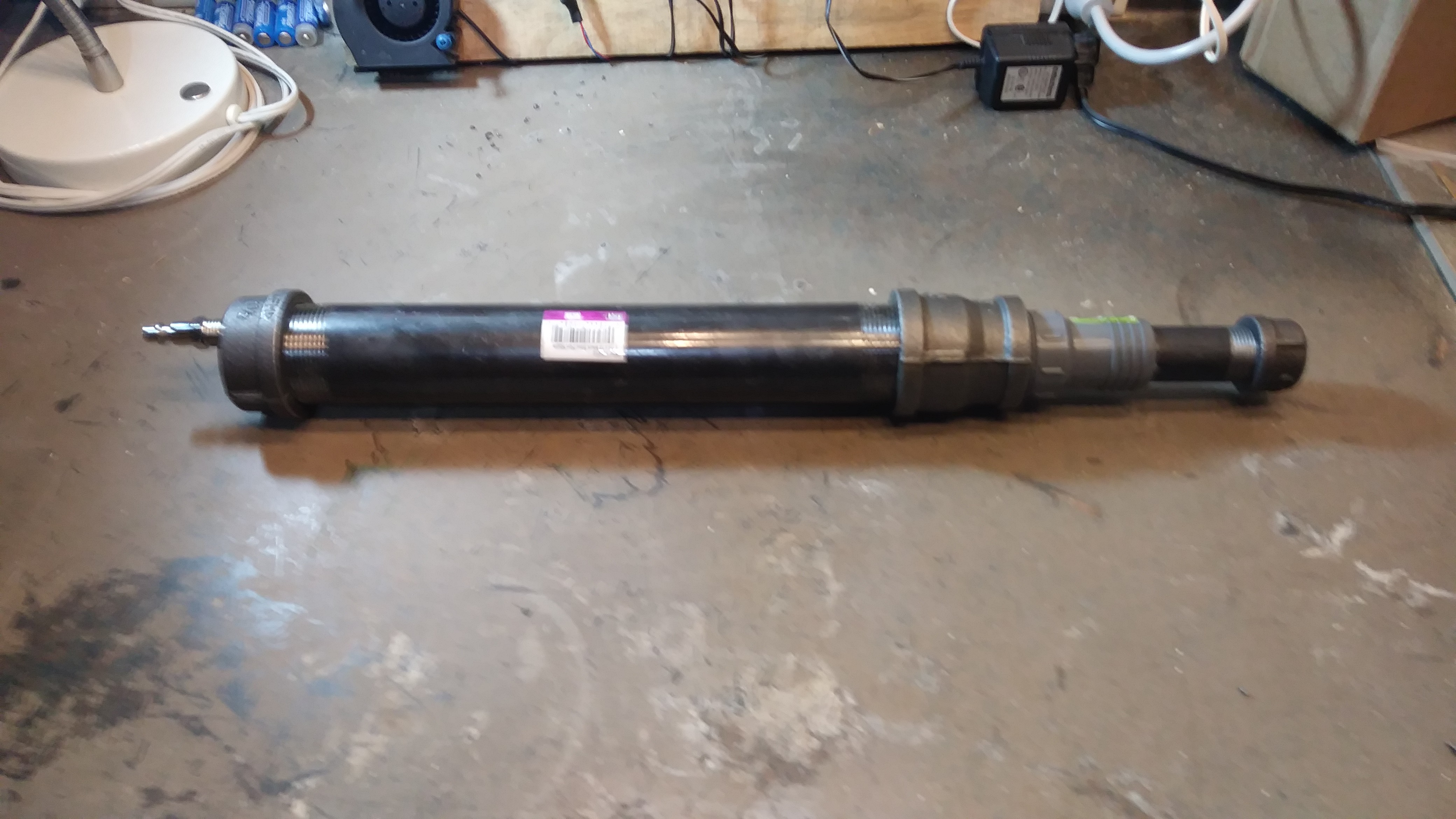
It's complete!
With the actuator completed, it was time for testing. It didn't take long to find out there was an issue. Too much air was leaking around the piston, and my wimpy compressor couldn't keep up. Despite that, I was able to get about 40 PSI in the cylinder, and it provided a good pushing action. I think this design will work well for the vehicle suspension system, but I need a better seal between the piston and the inner wall of the main cylinder. Stay tuned for part 2 where I'm going to try some options for making that all-important seal!
Discussions
Become a Hackaday.io Member
Create an account to leave a comment. Already have an account? Log In.