 Tim Wilkinson
The RoBonnet v0.3 is here. This is primarily a power test; a test to see if I'm capable of building a buck converter using the MP2315. Spoiler alert - no :-( At least, not quite.
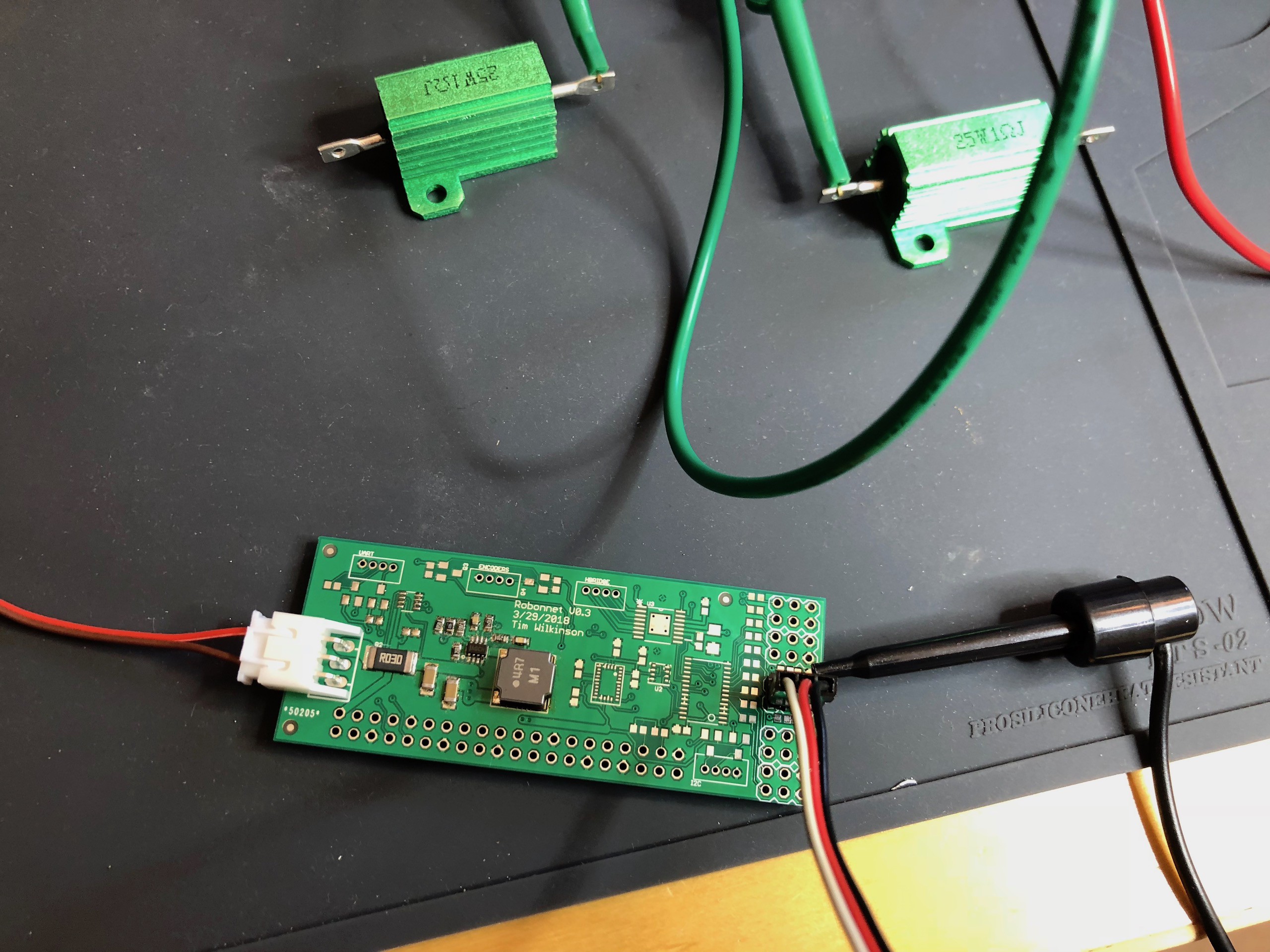
So the new board, shown above, is just populated with the basics necessary to test the buck converter: an MP2315, capacitors, random resistors to set the voltage level, and the main inductor. I carefully followed the data sheet instructions for part selection and layout because I don't understand these things so don't know what's important and what isn't.
When I initially power this up using my bench supply, it successfully regulated the range of input voltages I tried! Success? Turns out no. In the photo you see two 25W 1ohm resistor used to provide a simulated load of 2 ohms - so drawing 2.5 amps at 5V. As soon as I tried this, the regulated voltage dropped down to about 3V unless the input voltage was under 7.2V. To be honest I have no idea why, although it appears that the internal VCC regulator voltage also drops.
In an attempt to work out if I'd made a bad part selection, I scavenged various parts from some eBay MP2315 regulators that did work, but even when I swapped in those parts, my design failed in a similar way.
And so, I'm forced to assume it's my layout, and while I did try to stick with the data sheet layout, I definitely made some mistakes along the way regarding GND quality and some of the feedback paths.
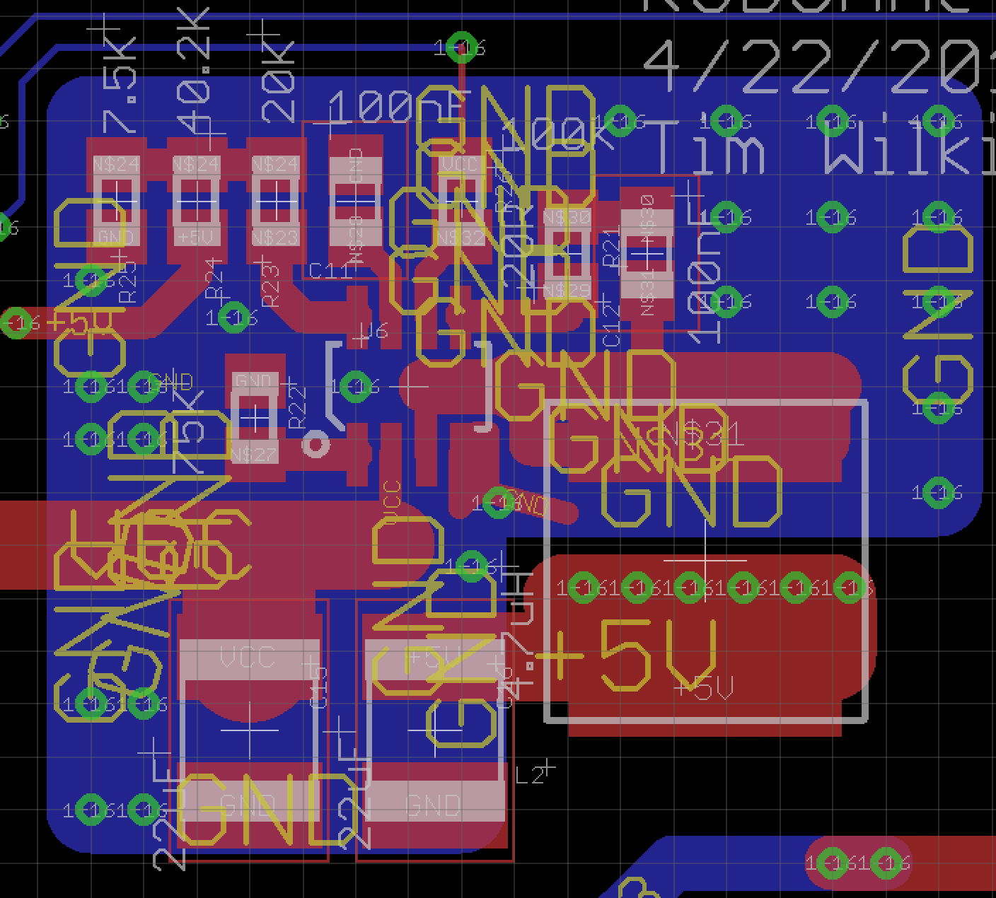
This, somewhat messy, screen capture above show the new layout, without the ground and power planes shown but with extra ground copper on both sides of the board. Let's see how this does.
Discussions
Become a Hackaday.io Member
Create an account to leave a comment. Already have an account? Log In.