 helge
helgeI've picked up meditation again - drilling, tapping, filing, sanding and lapping. One tends to get lethargic and lazy just watching youtube machinists do their thing; one of the few activities that get me in the mood is grabbing some stock and make it do things. One day I'll have a shop to call my own again. Meanwhile I occasionally sneak in half an hour at work while some experiment is running, so I appreciate your patience.
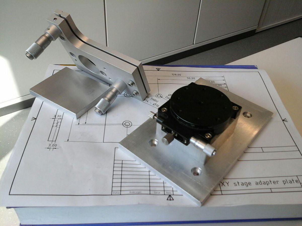
Building the machine could be designed planned and then executed with discipline but.. this is not that. So let's start in an unstructured manner by manufacturing and assembling the mechanical components:
- adapter plate to connect motorized XY stage and manual kinematic mount
- 25mm pedestal for clearance and rigid flat bolting face
- adapter plate to mount 2-axis pitch/yaw contraption to the rotating stage
Ok.. I admit I made drawings, telling myself that's so as to not look suspicious in the shop and to reduce the likelyhood of drilling and counterboring a mirrored hole pattern.
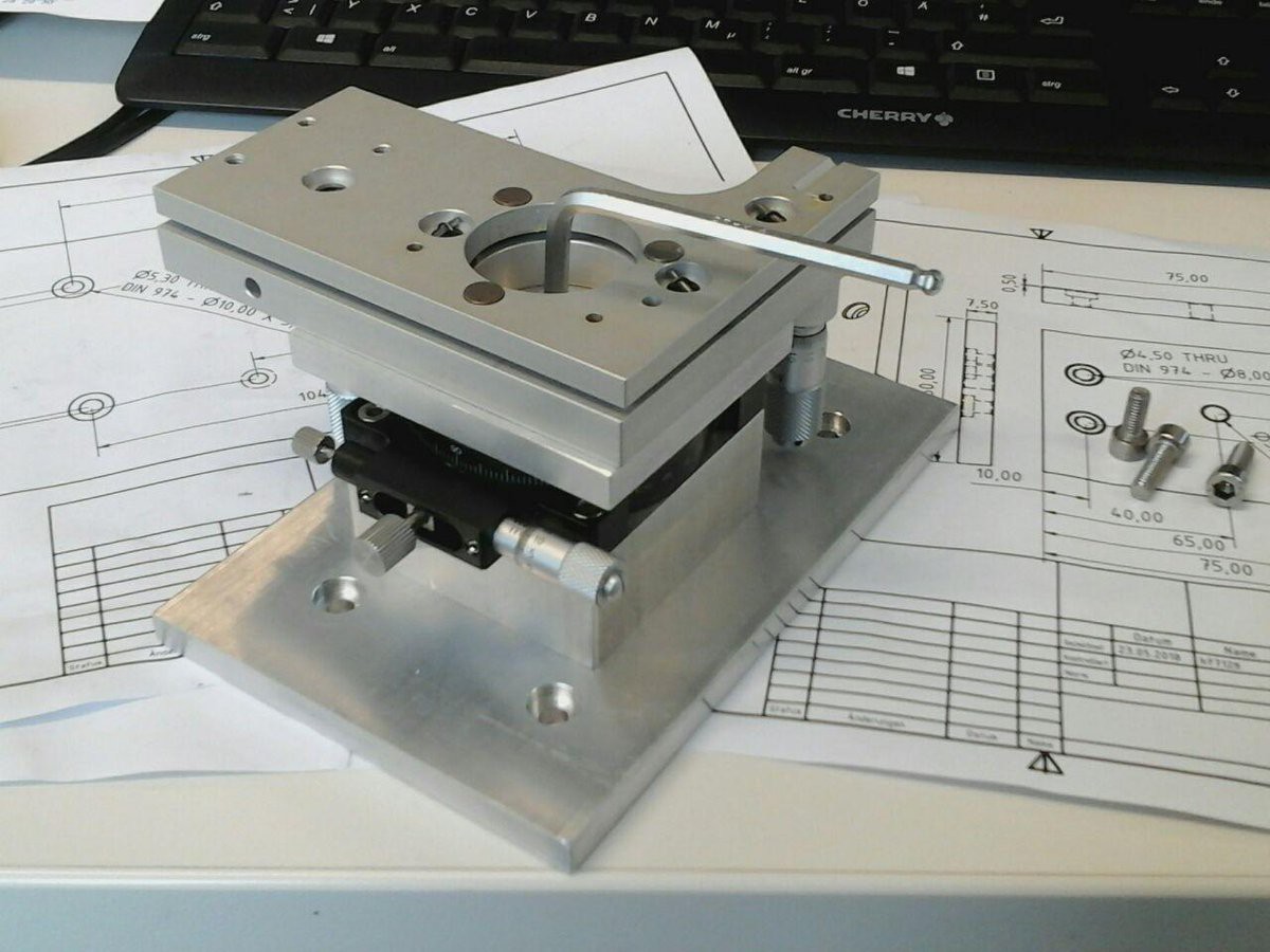
There it is, starring my nemesis, the chinese rip-off stage - raised to a level that establishes some clearance for the micrometer screws. The plates are only 7.5mm thick (no idea why, they ought to be 8mm extrusions) so I couldn't bring myself to do 4.5mm deep counterboring.
The rotating stage doesn't have axial spring preload yet and has to be set manually to minimal play so every minute deformation of the base or turntable results in it seizing up, promting me to spend more time lapping the mating surfaces.
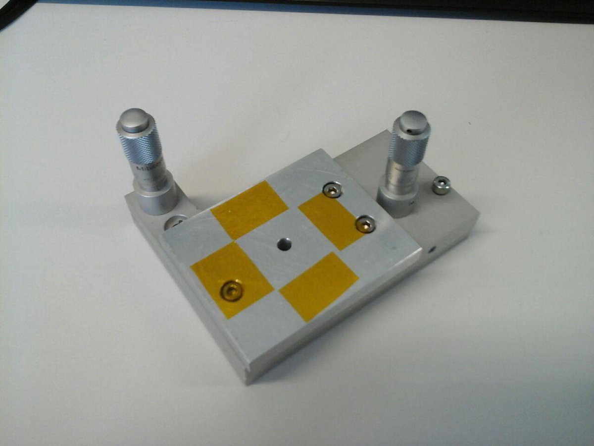
On the micrometer scale everything is a spring element so with the kinematic mount adapter plate done I created an annular pattern of kapton tape stripes, hoping to achieve proper seating without wobble:
The 2-axis tilt/yaw stage now bolts to the rotating mount turntable with a central M5 screw (flat washer + spring washer in between)
Unfortunately the turntable reacts to deformation most unfavorably. The fact that lapping the top plate reduced the issue points to the turntable being very susceptible to z-deformation with an azimuthal dependence.
On top of that it also seems to react to radially varying z-deformation to a lesser degree (convex warpage by pulling the screw upwards against the outer zone).
It is what it is, I guess. Maybe it's telling me I should use the outer M4 threads but they're not accessible with the plate in place, leaving just the central screw. I'm now using it to adjust play :D Mechanical parts have their own way of telling you what's right and what's wrong.
And there's the whole 5-axis stack bolted together:
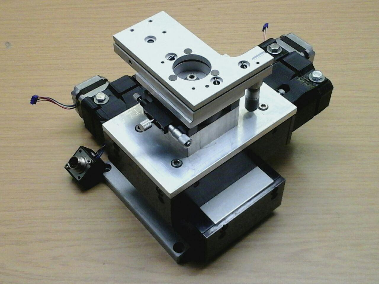
I'll have to leave the sketchy 3D printed stepper assemblies in place for now. They contain skew gear reductions coupled to the spindles... to be improved once the precision/repeatability test results are in.
See you around.
ps. Why build a 5-axis stage?
Ok, actually there'll be a sixth axis with a piezo actuator (focus in z direction).
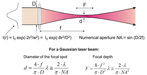
The cartesian axes are obvious. Tilt and yaw have to be adjustable (at least manually) to get the sample surface leveled. For lambda = 400 nm and NA = 0.85 we're looking at a focal depth of about 350 nm which is almost guaranteed to be violated by room temperature driven thermal expansion, vibrations and looking at the setup the wrong way. Wafer pieces are sufficiently flat for their edges to be used as reference features, enabling on-the-fly focus correction but you'll have to start with the object plane nearly level to within a few micrometers across a 10-20 mm wide sample. If there's still some room left for variability within the zone it's going to be consumed by the radially diverging field flatness error.
https://www.aao.org/munnerlyn-laser-surgery-center/basic-laser-properties
The motivation for the rotating stage is the need for re-alignment between processing steps, maintaining registration of pixel rows/columns without the need for interpolation and further loss of resolution.
Just hoping I don't have to upgrade all the axes to piezo positioning :)
Discussions
Become a Hackaday.io Member
Create an account to leave a comment. Already have an account? Log In.