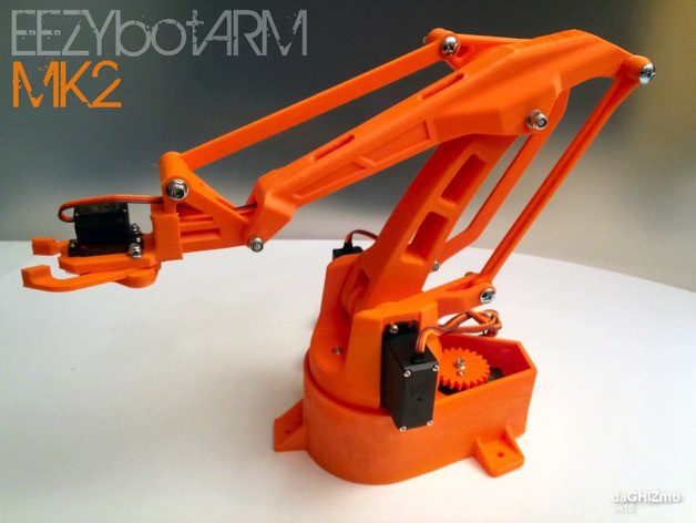
I decided to put my Prusa i3 MK2 to use and have been 3D-printing the parts for the EEZYbotARM MK2 robotic arm. This thing uses three larger MG995 or MG946 servo motors, in addition to a smaller plastic SG90 servo for the "grabber" (formally called an "end effector" FYI). Rather than wiring up a some messy circuit or buying something already available, I decided to make a PCB for the job of driving the servo motors. This gave me the opportunity to add something not available on existing solutions: a Wii Nunchuck connector.
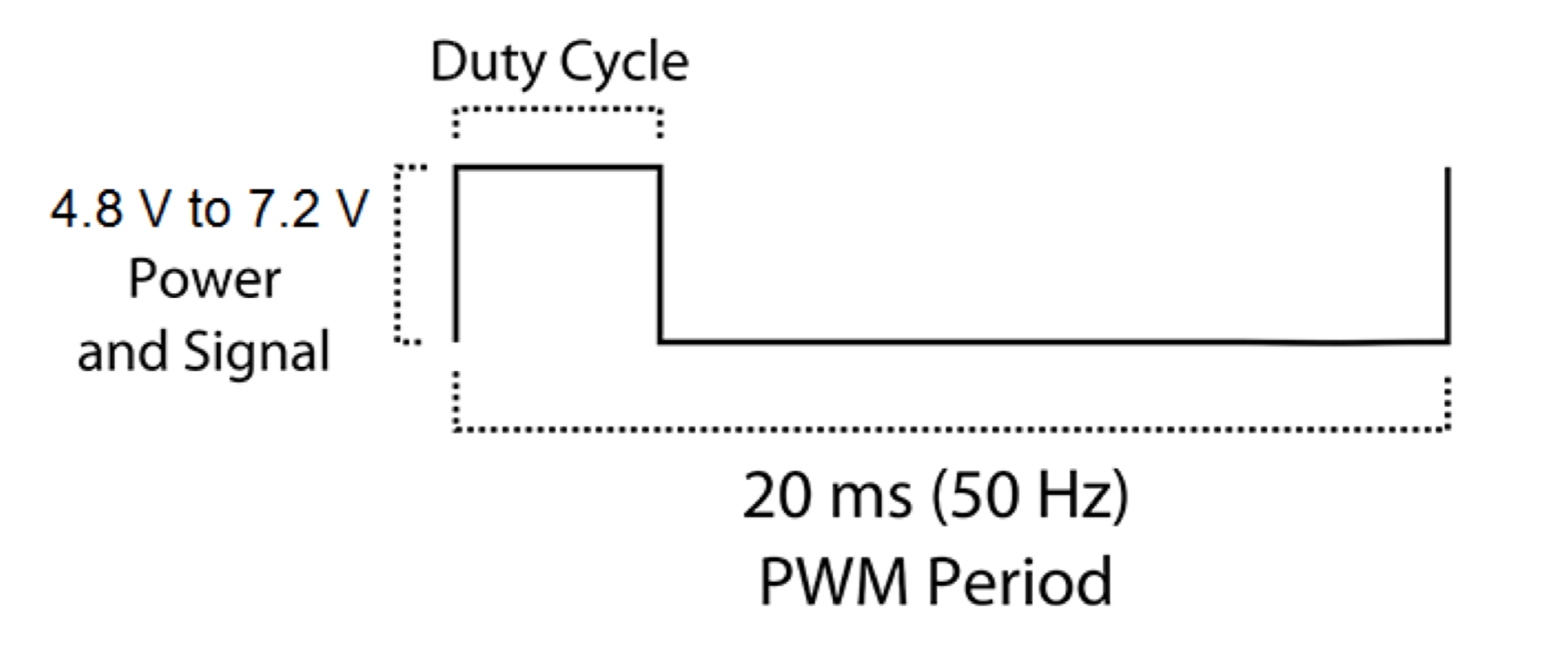
The servo motors are controlled using a PWM signal, and the manufacturer specifies the operating voltage at 4.8 V - 6.6 V. The STM32 Nucleo boards work at 3.3 V, and I have read that a 3.3 V PWM would likely work for driving a servo motor. However, to be safe I have added some FETs to translate the 3.3V PWM to 5 V.
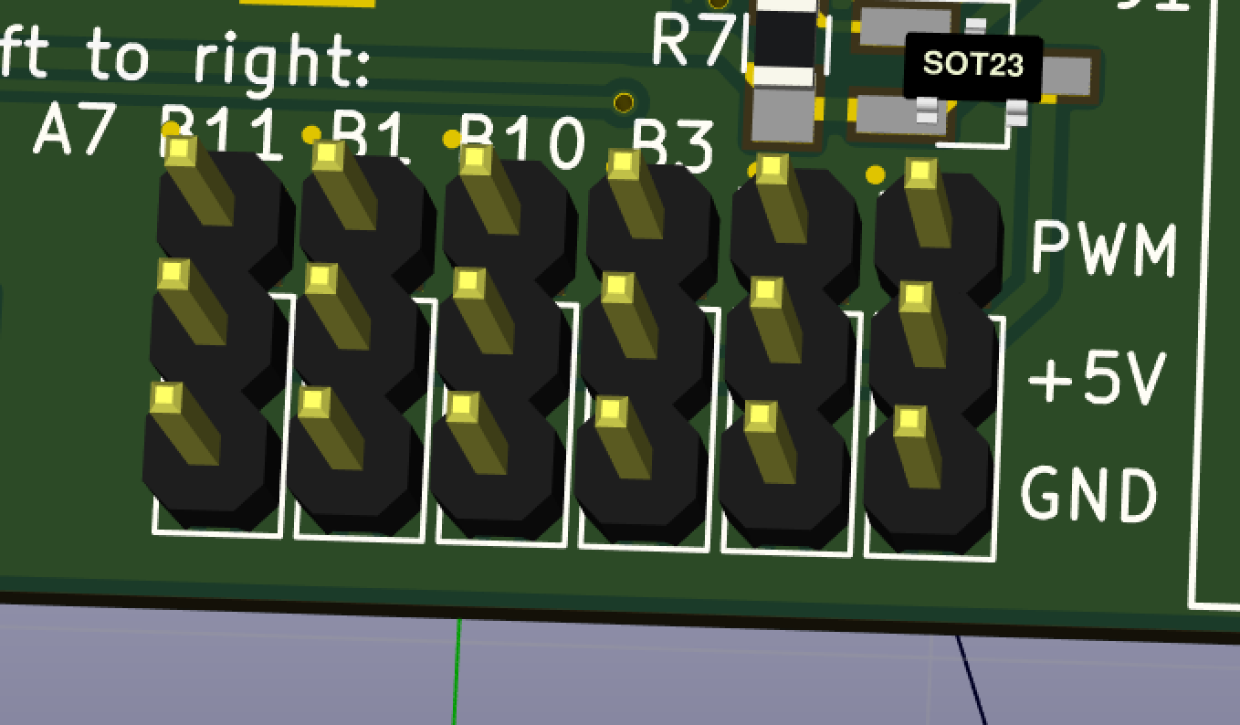
The board has standard servo connectors (a.k.a. 3-pin 0.254 mm headers) for up to 6 servo motors. There is also a power enable signal that connects the servos to the 5 V supply via a FET with a low on-resistance.
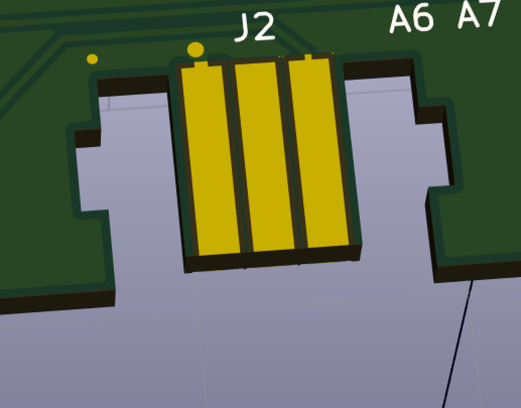
Lastly, I have added a Wii Nunchuck connector. This is basically just a PCB card edge connector that I duplicated from here. The Nunchuck uses a simple I2C interface, and I am planning to use it to control the robotic arm.
This PCB is an STM32 expansion board, so it uses the Morpho headers that work with Nucleo boards, similar to how shields work with Arduino. The first layout of the first revision is done and has been sent to get fabricated.
Discussions
Become a Hackaday.io Member
Create an account to leave a comment. Already have an account? Log In.