The revision 2 PCBs are have shipped but are expected to arrive on Tuesday, so unfortunately they won't make it for the Hackaday Prize robotics contest deadline. Meanwhile, I've been tweaking the firmware. The firmware is on Mbed, so you can compile it for other supported microcontrollers as well. I've been using the STM32L073 and STM32L476 MCUs, so these at least have the required PWM functionality on the correct pins.
The EEZYBot ARM MK2 uses three servos to control the arm and a fourth servo for the end effector. The Wii Nunchuck controller has a joystick and two buttons. This essentially allows control of three "axes". Two of these are from the joystick (up/down and left/right) and the third from the two buttons. Originally, my firmware used these three to control the three main servo directly, For example, moving the joystick up/down moved a single servo. This is easy to implement, but it is not very intuitive to use since the end of the arm does not move just horizontally or vertically, but rather along a more complex trajectory.
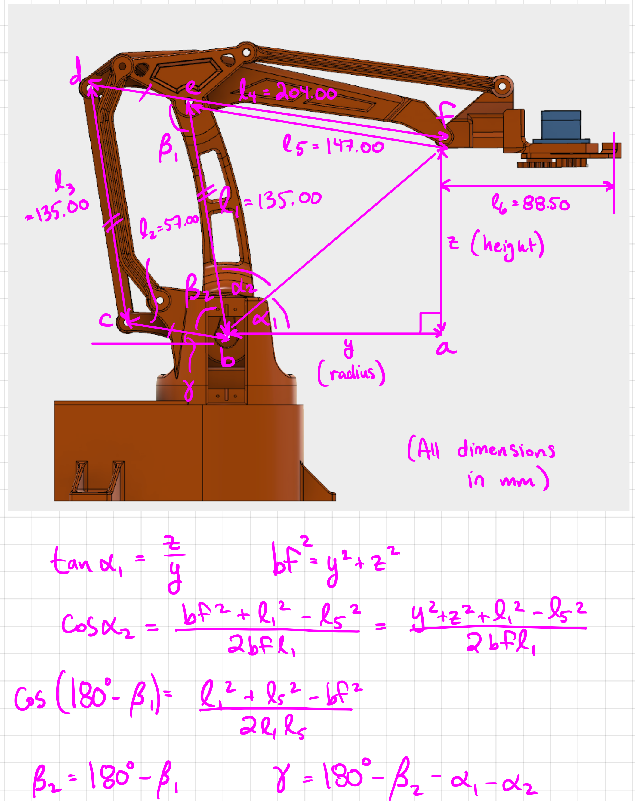
I thought it would be nice to be able to press up/down and have the end of the arm move just in the vertical direction. This is a little more complex to implement since it involves moving multiple servos and doing some math to figure out how they need to move. The math is just high school trigonometry, as shown in my sketch below. Essentially, I need to calculate the angles α (the sum of α₁ and α₂) and γ, which can be used to calculate the angles of the main arm (l₁) and the little arm labelled l₂.
This math is implemented in the pos_to_angle function:
void pos_to_angle(double *horz_angle, double *vert_angle, double radius, double height)
{
    double alpha1 = atan(height/radius);
    double bf_2 = radius*radius + height*height;
    double alpha2 = acos((bf_2 + L1*L1 - L5*L5)/(2*sqrt(bf_2)*L1));
    *horz_angle = PI/2 - (alpha1 + alpha2);
    double beta2 = acos((L1*L1 + L5*L5 - bf_2)/(2*L1*L5));
    *vert_angle = PI - beta2 - alpha1 - alpha2;
}
I made a quick video to show the firmware in action:
The firmware first allows you to calibrate, which involves positioning the arm so that the main arm is vertical and the other one is horizontal. Pressing SWITCH 2 performs the calibration, which saves offsets for each of the servo motors. Note that the firmware is written so that it works with the EEZYBot ARM MK2. To use other robotic arms, you would need to adjust the constants (e.g. l₁) and perhaps the math, if the arm has a different kinematic linkage.
Actually operating the arm is very intuitive. Up/down on the joystick moves the end effector horizontally. The two buttons on the back move it vertically, and left/right on the joystick rotates the arm around the base. To open/close the end effector, pushing the two buttons simultaneously activates another "mode" where up/down on the joystick now opens/closes the end effector.
I'm pretty happy with how the project has gone so far. Assuming that the revision 2 PCBs that are shipping fix the issue with the power enable signal, this project will be done!
Discussions
Become a Hackaday.io Member
Create an account to leave a comment. Already have an account? Log In.