This weekend has been quite the journey. With my wife & kid out of town for a few days and left to my own devices, I ended up working myself sick. Literally. :/
Saturday was spent drudging through failure, frustration, & a nasty flu. But only a couple days later I have finally accomplished enormous success!
The Mug-O-Matic (MoM) can now successfully draw with G-code using a simple replicatable toolpath! Leveraging a processing program & gcode reader based on work by Makerblock, Heindal, & Oliv4945, I had to modify their work significantly to suit my specific needs. In the end the path is: Use Repetier Host + Slic3r to slice a flat 3d model & export gcode to desktop, Use Processing to send data over serial (usb tethered), have the arduino interpret said data line by line to print. Video to follow. On the downside more tuning is clearly required, the drawings resulting from gcode are much sloppier than I had hoped and the act of drawing is slow. Too soon to say how clean I will be able to get it. Im still happy though!
Almost as good is that I successfully completed the line segmentation algorithm. Now when you tell the device to draw a long line from one side to the other, (at any angle/direction) it will segment that line into the minimum draw-able resolution of 1mm and move the specified distance in the maximum number of increments. The result is a slower motion that negates the effects of rotating mass and prevents target overshoot!
The backlash compensation code is also up and going successfully. The effect is subtle because the backlash was subtle, but it works and I am satisfied.
Other learnings & updates in bullet form:
*Unfortunately, this device can never do stall detection as I had originally hoped. While hobby servos do use potentiometers, they are not physically wired to provide feedback to the arduino. The feedback is simply unavailable. (Arduino servo.read command just tells you the last position you wrote to the servo, not the actual angle it is which may differ if the device as been stalled.)
*I am designing a new Tiny_CNC_PCB specific for this project based on the MePed board by Scott P. Though his work is great for this, there are some minor variations for cost & fit & function that I want to implement. To be honest I have never designed or ordered a PCB in my life, but have wanted to learn the skills. This has been a great opportunity to learn KiCad and pcb design via remixing rather than starting from scratch. So I thought I had it finished and I even have a prototype supplier lined up, only then I decided that I need to update the design a bit more...This perfectionism is a trend with me that is great for getting a job done well, though timeliness can suffer. This is what has made the 3D models take so long to complete.
*My 3d modelling has also been slowed by the fact that designing all 60 components to be modular and function with each other as a set means that I have to be aware of every possible mechanical configuration for interferences and such. Physical testing with all parts in hand of the latest rev is very important. Often I find problems caused by very subltle issues like two seemingly perpendicular surfaces actually being 179.5 degrees apart, thereby stalling a hinge. The devil is in the details!
*The software processing.org/ is really powerful stuff for easily making a custom robot controller GUI and I am definitely going to spend more time learning the intricacies at some point. For now knowing the basics is adequate.
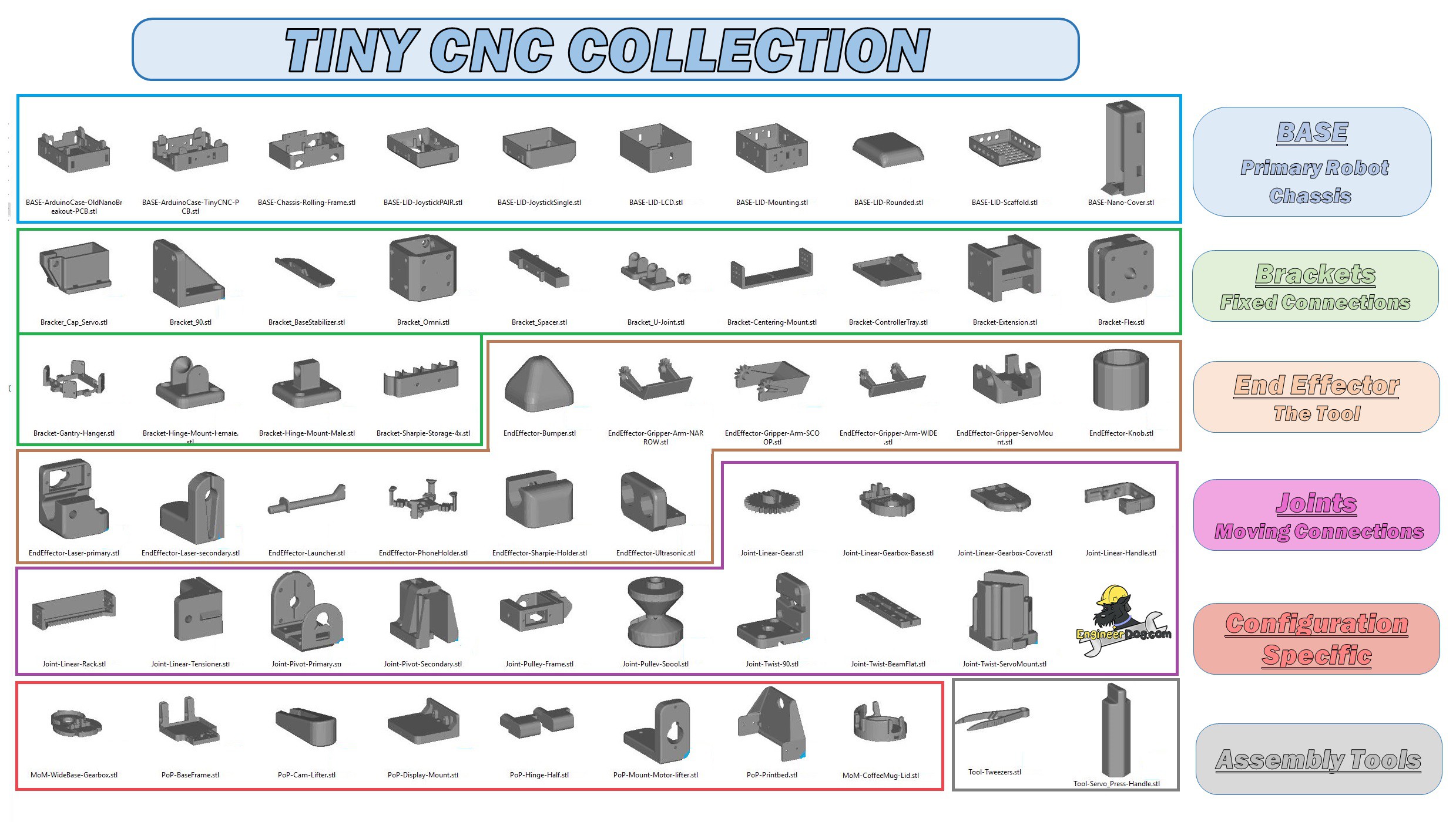
*I have been releasing 3dmodels to thingiverse as I get the time to photograph the assembly process and watermark the images. (Yes this project IS still 100% open source, and if people want to make their own from scratch you are welcome to do so, but the attribution aspect is important to me.) Here is that growing 3d model collection:https://www.thingiverse.com/MechEngineerMike/collections/mugomatic-tiny-cnc-collection
*Here is the latest artwork to help describe how the components of this collection go together.

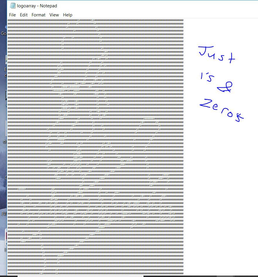
*Also of note: As an alternative to gcode drawing I am developing dot matrix drawing capability in parallel as a hedge against failure. This thing WILL draw custom stuff one way of another :D Below is an array of 1 & zeros generated from an image of my blog logo. My experiment suggest that I will be able to write a program that operates very much like a mechanical typewriter moves, line by line seeking that 1 to make a dot. This method will produce discontinuous lines BUT it wont smear either.
As you can see the words are simply scrambled in the process, the logo is too detailed to be scaled as a whole down to a 1mm minimum movement scale.

 Michael Graham
Discussions
Become a Hackaday.io Member
Create an account to leave a comment. Already have an account? Log In.