Included here are a few wave forms of the TS50's AC output.
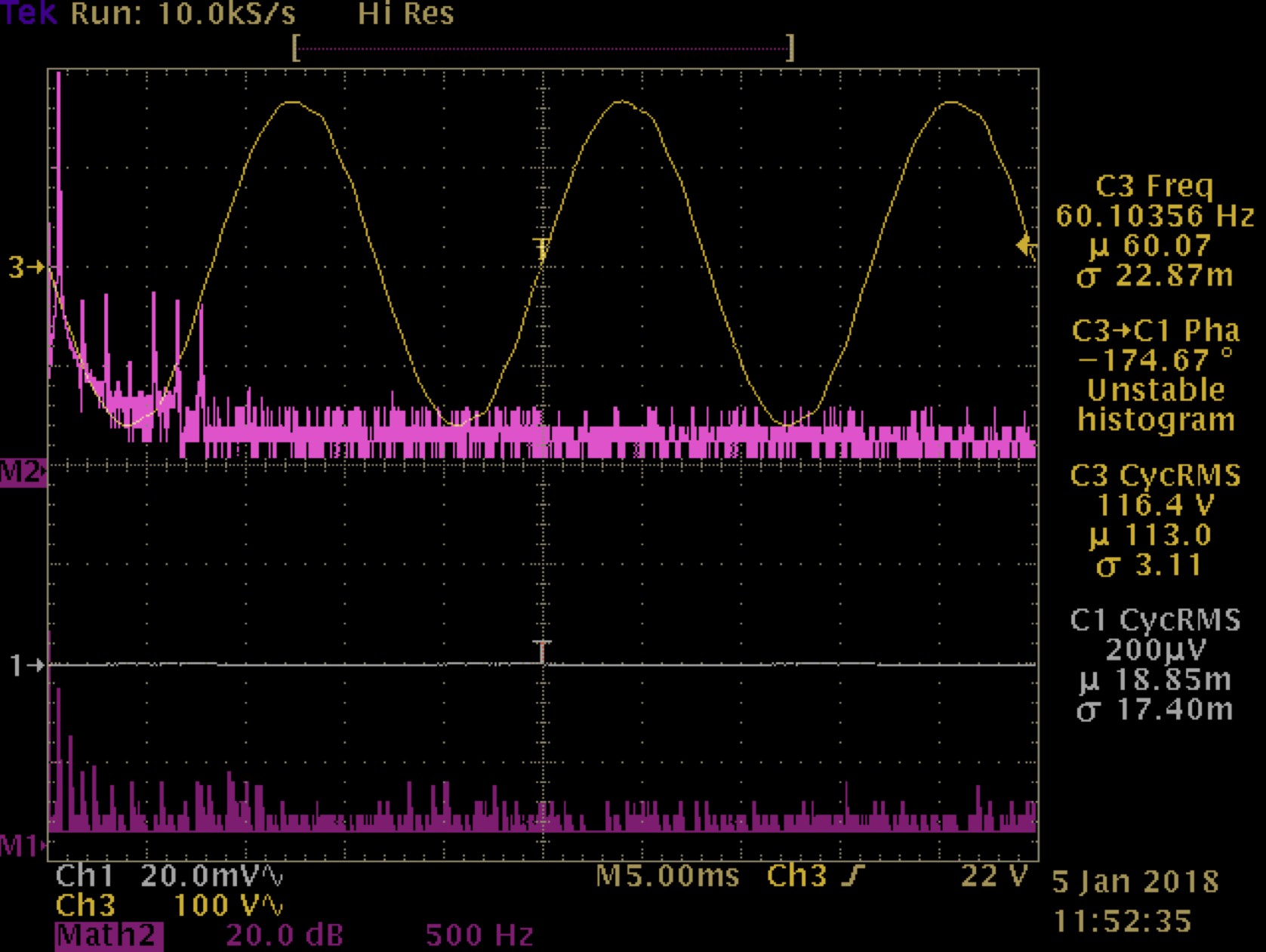
First up is the output at no load. Channel assignments:
- CH1=current, 100mV/A
- CH3=voltage
- M1=FFT current
- M2=FFT voltage
Same setup but with 40W load (incandescent bulb).
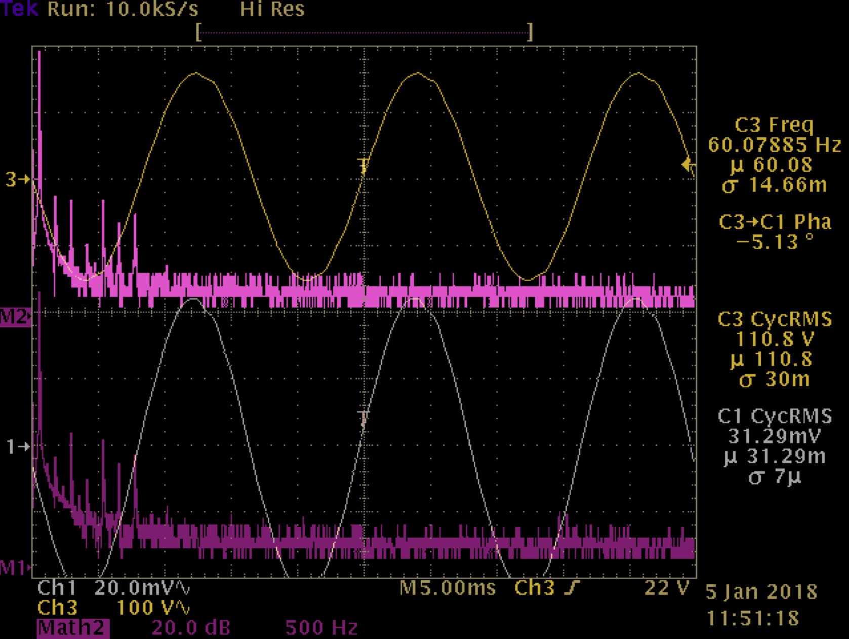
In both the harmonics are concentrated below 150Hz and, the three higher harmonics are likely aliases. The FFTs I've taken of the utility power in my home have more harmonics than this. Per the log covering the sine module's operatin, the reason that the FFT is not square is because the frequency isn't exactly 60Hz.
Last one shows a higher power inductive load. CH1=current (185mV/A), CH3=voltage. The TS50 is powering a Dremel 3000 with the speed control at position 6 (out of 8) under no load.
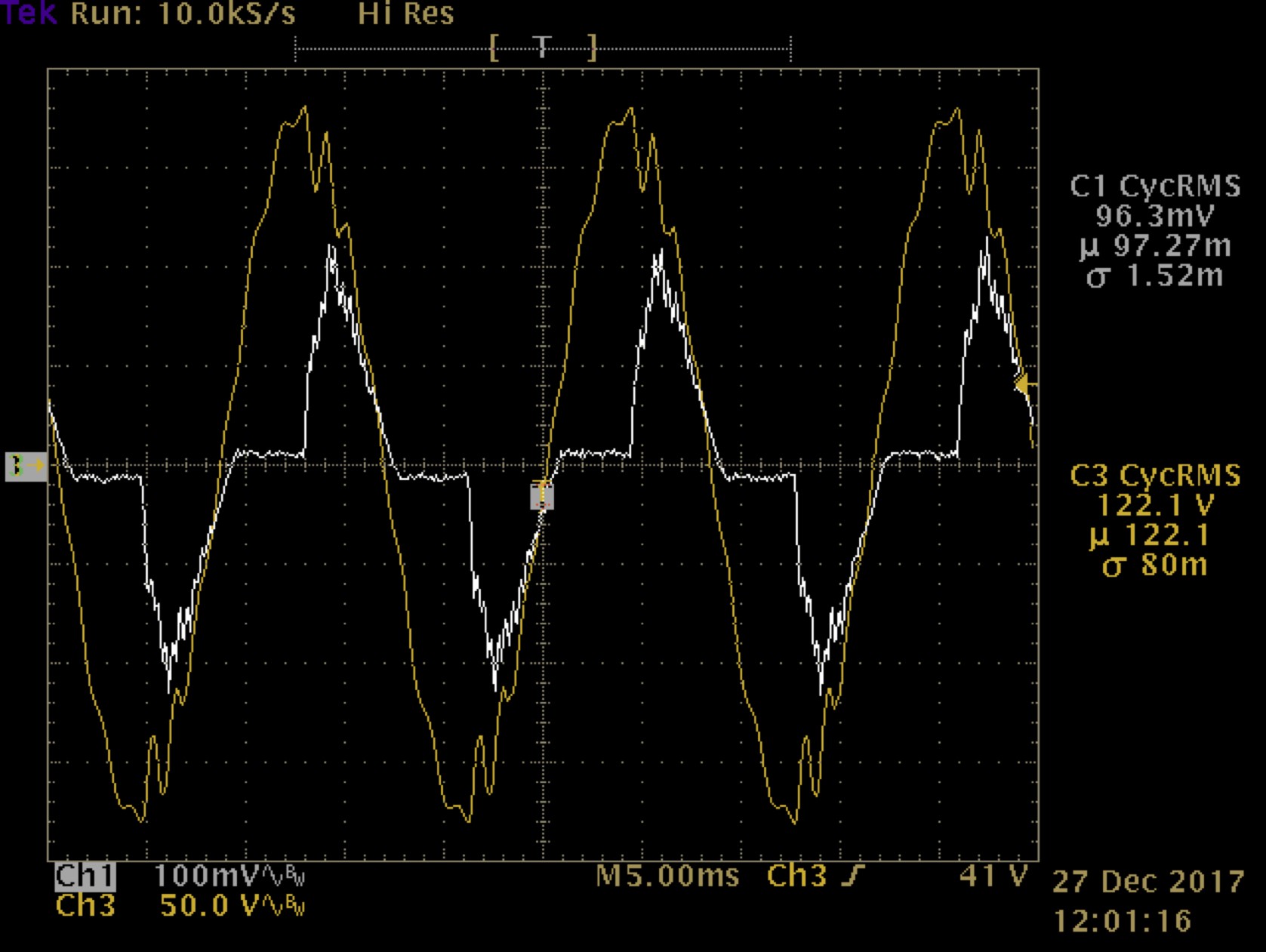
Visually estimating phase shift, peak current is ~ 1.2A which roughly equates to 192W peak and 64W RMS. The distortion in the voltage waveform is due to the relatively high impedance of the inverter and not the sine generation / output method itself. It's a good demonstration that regardless of an inverter's continuously rated output it must have a substantially higher peak output capability.
Otherwise, the current waveform & phase shift match what was observed with the Dremel powered by the utility.
Discussions
Become a Hackaday.io Member
Create an account to leave a comment. Already have an account? Log In.