 tlalexander
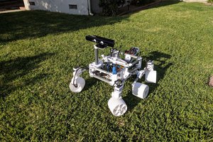
Rover's CAD work is done in OnShape, so anyone can fork the design for free. It's licensed CC0 so it can be used for any purpose with no restrictions. Get started with the files here:
https://cad.onshape.com/documents/456d1f84fb77a5beb824aec7/v/a2bf739ac2020b4ce6d3fa4e/e/5dbf6543a003f8263f184ade
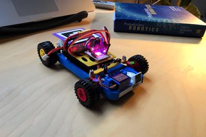
Rover runs an open source licensed Python stack I wrote myself, and uses a Raspberry Pi for basic control. (Future versions may use a Jetson TX2 or similar.)
https://github.com/tlalexander/rover_control
A video showing Rover V2's rolling chassis is here:
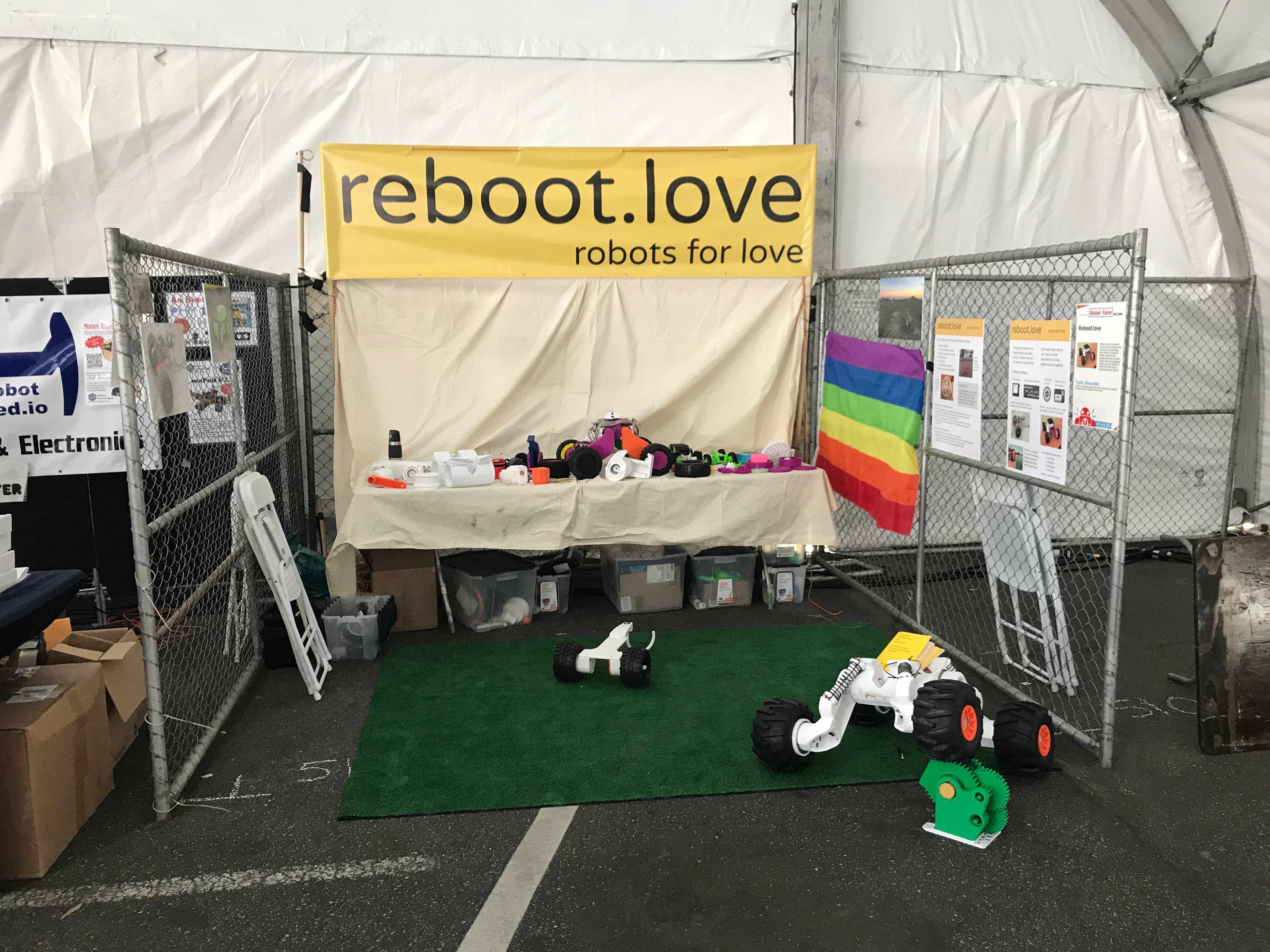
Rover has a parent website, called Reboot.love, with a discussion board where people can talk about 3D printing useful robots and what it all means. Visit that at http://reboot.love/
My long term goal with reboot is to make many useful open source robots, and then attempt to start communities where the robots support the survival of the community members by making them food and other useful goods. I discuss this concept in my essay The Machine. http://tlalexander.com/machine/
Near term, I will use Rover to experiment with low cost sensing for robotics using simple cameras as the primary sensor in localization, obstacle avoidance, and navigation systems.
I started Rover V1 in Oct 2017 and had it driving by December. Work on Rover V2 started around the beginning of April 2018.

 Roger
Roger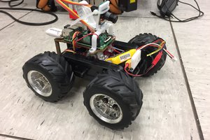
 Piotr Sokólski
 Crypto [Neo]
YESSS Taylor, great to see this in the wild! Oh, I've got a 1kg roll of petg 2.85mm I accidentally ordered that's yours if you want it! Print 1/8th of one of your parts :P