 Dave's Dev Lab
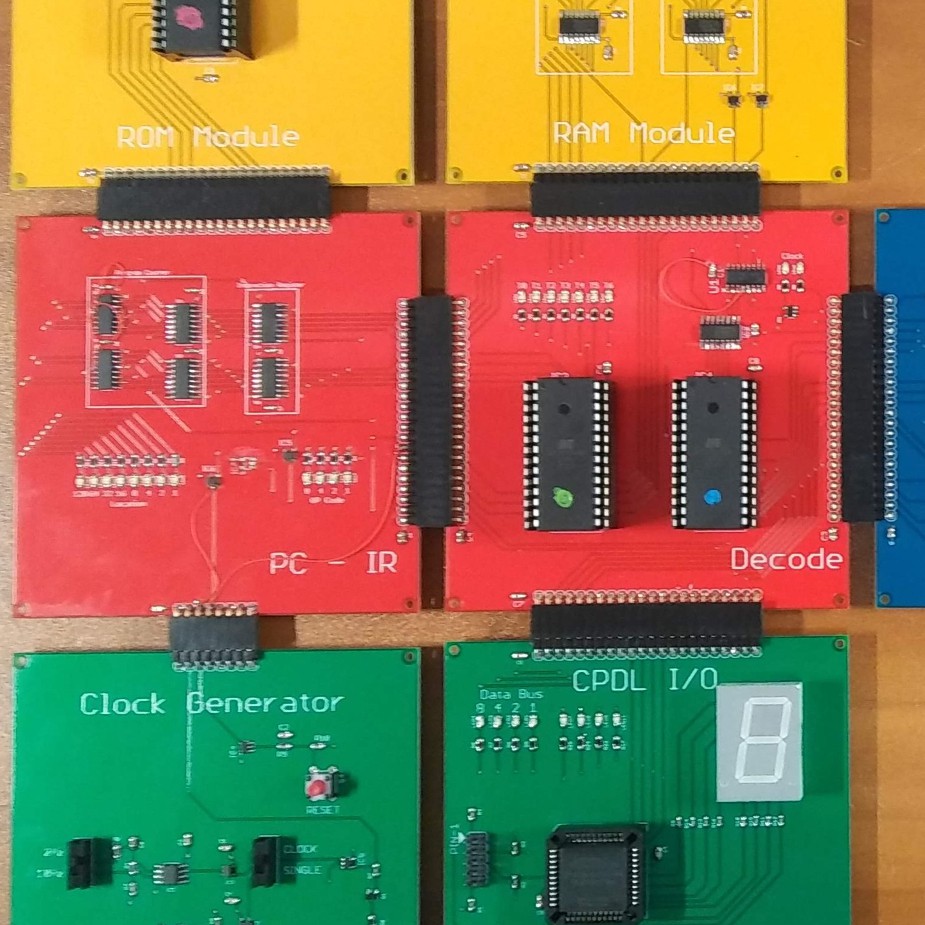
In the first revision of the DDL4-CPU, the Clock Generator Module connects to the Program Counter / Instruction Register (PC/IR) Module via a single row 8 pin header. Only 5 signals are used out of the 8. I left room for expansion and testing. The rest of the modules are connected together with a single row 22 pin header. The pinout of the header varies a little between board but there is a loose format to the pinout:
1 - VCC
2-9 DATA_BUS[8:0]
10-19 Control Signals
20 - Reset
21 - Master Clock
22 - GND
While the Clock Generator Module only needs 5 pins, it is the one module that I didn't use the 1x22 header, and to be perfectly honest, it looks out of place. The 1x8 header that it currently use is more than enough, however it just "looks" out of place, so for consistency and pure aesthetics, I am replacing it with the 1x22 header on revB of the design...
Discussions
Become a Hackaday.io Member
Create an account to leave a comment. Already have an account? Log In.