Alojz Jakob
Greetings!
Today we are going to update Tamaguino with a shiny new huge 2.7" OLED display, kindly provided by DFRobot!
As you may already know, Tamaguino was one of my first Arduino projects and my first game developed to run on a microcontroller. It is a clone of Tamagotchi virtual pet, which were very popular in the 90's, and gaining popularity in last few years too!
First version of Tamaguino used well known 0.96" I2C OLED that is widely available and used by many electronics hobbyists.
Tamaguino has it's own website: https://alojzjakob.github.io/Tamaguino/.
There you can find detailed information and schematics, source code and related libraires, 3D printable cases and much more. It was ported to Arduboy too! ;)
Now that you know the brief history of Tamaguino, lets make it shine on this new big OLED!
 Ian Black
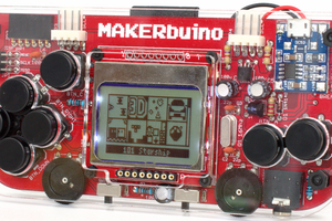
 CircuitMess
 Lixie Labs