Waveforms using Pi DMA
ServoBlaster, pigpio, pi-blaster and `yapidh` all operate on the same principle. The Raspberry Pi lacks a generic timer-based trigger for the DMA engine, but it does have peripherals which can request data at a continuous rate (the "feed me" signal!). We use these peripherals to trigger DMA transactions at a constant known rate, in order to provide accurate timing. By making the DMA engine write to the GPIO set/clear registers, we can use this "trick" to generate GPIO output (or input) very consistently, and very precisely.
The DMA engine reads lists of "control blocks" (CBs), with each CB describing a DMA "job". The control blocks are linked together, and the DMA engine will fetch the next in the list once its finished processing the current job.
So, there's two parts to this trick:
- Set up a peripheral (PWM or PCM) so that asks the DMA engine for data every N microseconds
- Set up a list of DMA control blocks, with "useful work" (gpio set/clear) interleaved with control blocks which just feed the PWM/PCM
For the purposes of the explanations below, I'm going to assume that the PWM peripheral is used, and is configured to request a new sample every 10us.
Servoblaster/pi-blaster
ServoBlaster and pi-blaster take a straightforward approach. They build a long list of DMA CBs, which form a loop. Each "sample" consists of two control blocks - one which feeds the PWM/PCM, and the other which writes to GPIO.
When the PWM/PCM sends a "feed me" request, the DMA fetches the next CB, which writes to the GPIO set/clear register to make the appropriate output. However, because this CB doesn't "feed" the PWM, the "feed me" request is still asserted, and the DMA immediately fetches the next CB. This CB writes some data to the PWM, which satisfies its hunger. The PWM spends the next 10us outputting a sample - and 10us later, it asserts the "feed me" signal again, and the process continues.
This approach works well.
The implications are that:
- Every single "sample" means two DMA CBs have to be fetched from memory (32 bytes each - so a 10us/sample that's only 6.4 MB/s, which is realistically pretty insignificant)
- The number of CBs you need is directly related to the length (not the complexity) of your wave segment
- Any update of the waveform has to be done while the DMA is "live" and currently reading the CBs. This means it can be hard to guarantee your changes get in at the right time.
yapidh
`yapidh` (and I think pigpio's waveform generators, but I didn't really understand the code) takes a slightly different approach: instead of having a single loop with two CBs for every single sample, `yapidh` uses one CB for each delay, rising edge and falling edge respectively. This means that if you're generating a single square wave, you only need 4 CBs (actually a couple more for "fences" discussed below), regardless of how long the square wave's period is.
To achieve this, each "delay" CB is set up to transfer multiple samples. For a PWM tick-rate of 10us, a 100us delay would be represented as a CB with length = 10. That means that the DMA engine will keep using the same CB 10 times, once every time the "feed me" signal is raised, and it will take a total of 100us for the DMA to process that CB.
On-the-fly CB generation
The other difference with yapidh, is that it generates the CB chains 'on the fly'. For the sake of argument - lets say we're generating 16ms chunks of waveform at a time (but any length is possible).
yapidh uses the idea of "event sources" to figure out how to generate the CBs. It can have an arbitrary number of sources, and each source only needs to do two things:
- Tell yapidh how long it is until its next rising or falling edge
- What pins should be set/cleared at that time
yapidh then builds "chunks" of CBs, by generating delay/rising edge/falling edge CBs until it reaches the desired chunk length. It then links that new chunk on to the end of the one the DMA engine is currently processing. If any delays are split across a chunk boundary, then that's handled automatically.
Example yapidh program (Quickstart)
$ git clone git@github.com:usedbytes/yapidh.git
$ cd yapidh
$ make
$ ./yapidh > out.vcd     #Wait some time, then Ctrl+C
^C
$ pulseview -I vcd -i out.vcd
So how do you actually use yapidh? well I'd like to wrap it up into some useful tools - like "stepperd" (servod for stepper motors), but for now you can use the code directly. This example can be found on the 'example' branch in github.
Here's a a full example program which generates two square waves, with frequencies of 1 kHz and 3.333 kHz.
#include <stdbool.h>
#include <stdio.h>
#include <string.h>

#include "platform.h"
#include "types.h"
#include "wave_gen.h"

struct square_wave_source {
    struct source base;

    int pin;
    int period;
    bool rising;
};

static int square_wave_source_delay(struct source *s)
{
    struct square_wave_source *ss = (struct square_wave_source *)s;

    /* Next event is always period / 2 ticks away */
    return ss->period / 2;
}

static void square_wave_source_event(struct source *s, struct event *ev)
{
    struct square_wave_source *ss = (struct square_wave_source *)s;

    ev->channel = ss->pin;
    if (ss->rising) {
        ev->type = EVENT_RISING_EDGE;
    } else {
        ev->type = EVENT_FALLING_EDGE;
    }
    ss->rising = !ss->rising;
}

int main(int argc, char *argv[])
{
    int ret = 0;

    struct square_wave_source sq_1kHz = {
        .base = {
            .get_delay = square_wave_source_delay,
            .gen_event = square_wave_source_event,
        },
        /* 10us tick by default - 100 * 10us = 1ms, 1 kHz */
        .period = 100,
        .pin = 16,
    };

    struct square_wave_source sq_3_33kHz = {
        .base = {
            .get_delay = square_wave_source_delay,
            .gen_event = square_wave_source_event,
        },
        /* 10us tick by default - 30 * 10us = 300 us, 3.333 kHz */
        .period = 30,
        .pin = 19,

        /* Start this wave out-of-phase */
        .rising = true,
    };

    struct wave_ctx ctx = {
        .n_sources = 2,
        .sources = {
            &sq_1kHz.base,
            &sq_3_33kHz.base,
        },
    };
    uint32_t pins = (1 << 16) | (1 << 19);

    struct platform *p = platform_init(pins);
    if (!p) {
        fprintf(stderr, "Platform creation failed\n");
        return 1;
    }

    ctx.be = platform_get_backend(p);

    while (1) {
        ret = platform_sync(p, 1000);
        if (ret) {
            fprintf(stderr, "Timeout waiting for fence\n");
            goto fail;
        }

        wave_gen(&ctx, 1600);
    }

fail:
    platform_fini(p);
    return ret;
}
I used the VCD backend (see Testing backend below) to generate a VCD file, and opened that in Pulseview, instead of using the Pi DMA:
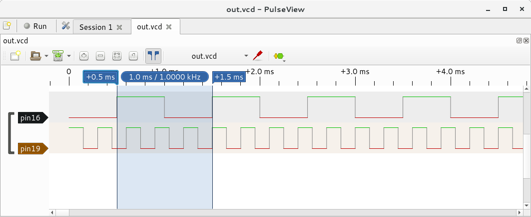
Wave generation Algorithm
The core yapidh algorithm is quite straightforward:
/* Generate a wave chunk, with maximum length "budget" */
void wave_gen(struct wave_ctx *c, int budget)
{
        int i, min;

        while (budget) {
                min = budget;

                for (i = 0; i < c->n_sources; i++) {
                        if (c->t[i] == 0) {
                                /* This source is ready to generate an event */
                                struct source *s = c->sources[i];
                                c->be->add_event(c->be, s);
                                /* Find the time until the next event */
                                c->t[i] = s->get_delay(s);
                        }

                        /* Keep track of when the next event is */
                        if (c->t[i] < min) {
                                min = c->t[i];
                        }
                }

                /* Delay until the next event */
                c->be->add_delay(c->be, min);

                /* Reduce all the remaining delays */
                for (i = 0; i < c->n_sources; i++) {
                        c->t[i] -= min;
                }

                /* Reduce the remaining time available in this chunk */
                budget -= min;
        }
}
It simply keeps track of when the next event is due for each event source, and generates a delay equal to the nearest event. Then generates whatever events are due, and finds the next nearest.
Synchronisation and double-buffering
Generating the wave chunks is one thing, but they aren't much use unless we can get the DMA to actually run them. To do that reliably, we need synchronisation, for two reasons:
- We don't want to generate "chunks" way into the future, because we want to be able to update the waveforms (e.g. motor speed) regularly
- We need to make sure we generate the next chunk in time to add it to the DMA, before the DMA finishes the current chunk.
To achieve this synchronisation, we use a "fence". Fences are a common concept in computer science - especially graphics, where synchronisation to frame boundaries is important. It's effectively a traffic light, represented by a variable.
When the fence is created, it's like a red light. You make the code keep checking the variable, until it goes "green", and then the code can continue. In yapidh's case, fences are simply CBs which write a value to a location in memory. When the DMA processes the fence CB, it causes the DMA to write a value ('1') to the fence location - the code can keep checking the location until it sees it is a '1', which means "green light, go!".
So, at the beginning of every wave chunk, yapidh inserts one of these fences. Then it adds the chunk on to the end of currently processing one. Then, it waits on the fence it created, and once that fence is 'signaled' (goes green), it generates the next chunk of waveform.
This solves both of our problems. 1) We don't get too far ahead, because we always wait for one chunk to start before we generate the next, 2) Because the fence signals at the start of the chunk, we have a whole chunk's worth of time to generate the next one.
You may have often heard people saying you can't do "real time" on a Pi because Linux isn't a real-time OS. While this is technically true - if a chunk is 16ms long, then it's very very very likely that you'll manage to generate the next chunk before it's too late (especially if you make your thread high priority). Shorter chunks will make you more likely to miss the deadline, and longer chunks less likely.
Performance
So, that's the theory out of the way. How does it work in practice?
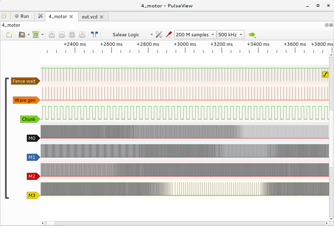
Well, below we can study some logic analyser traces of yapidh generating stepper motor drive pulses for 4 stepper motors simultaneously, with some extra added debug information:
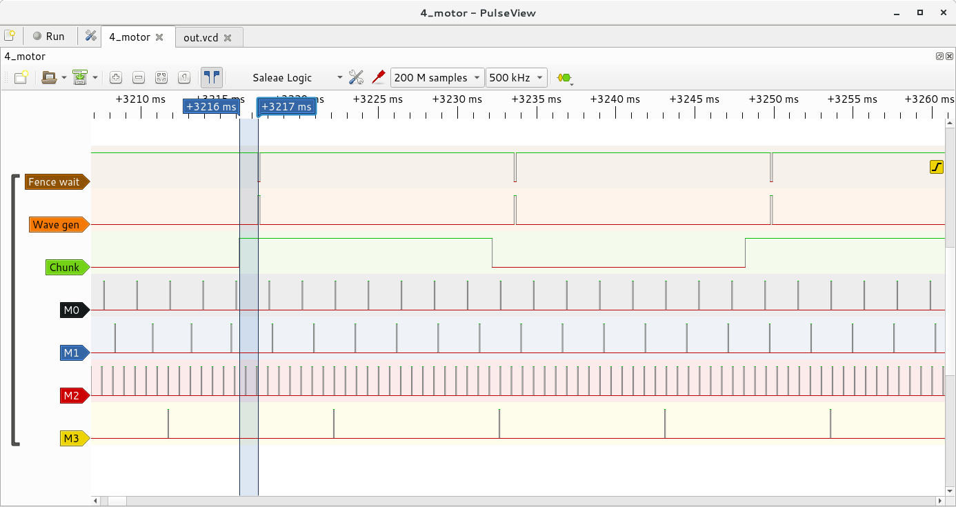
Scheduling latency
First, let's see how much of a problem "Linux isn't a real-time OS" is:
Each edge in the "Chunk" (green) row represents the start/end of a wave chunk, and is generated by a DMA CB which toggles the "Chunk" GPIO. When the "Fence wait" (brown) line is high, this means that the code is sat at a red light, waiting for the fence to signal.
The markers on the trace show the time delay between the fence getting signaled by the DMA HW, and the yapidh process getting woken up to start generating the next chunk - in this case it's ~1.4ms, but it fluctuates a little. By default the code checks the fence every 4 milliseconds, so if you get really really unlucky, the worse case you'd expect here is ~4-5 milliseconds.
So, with a maximum of 4-5 milliseconds of scheduling latency (and you can increase the polling frequency to reduce this, at the expense of higher CPU load), that leaves us 11-12ms to generate the next chunk at get it added to the DMA - loads of time!
Full disclosure, for this trace, my yapidh process was set to "real time" priority - if you have a lower priority, you'll see more jitter and longer delays.
I also ran this test-case at the same time as the GPU example "hello_videocube" which textures a Big Buck Bunny video onto a cube, to make sure that a heavy GPU load isn't going to interfere with yapidh - it was rock-solid throughout.
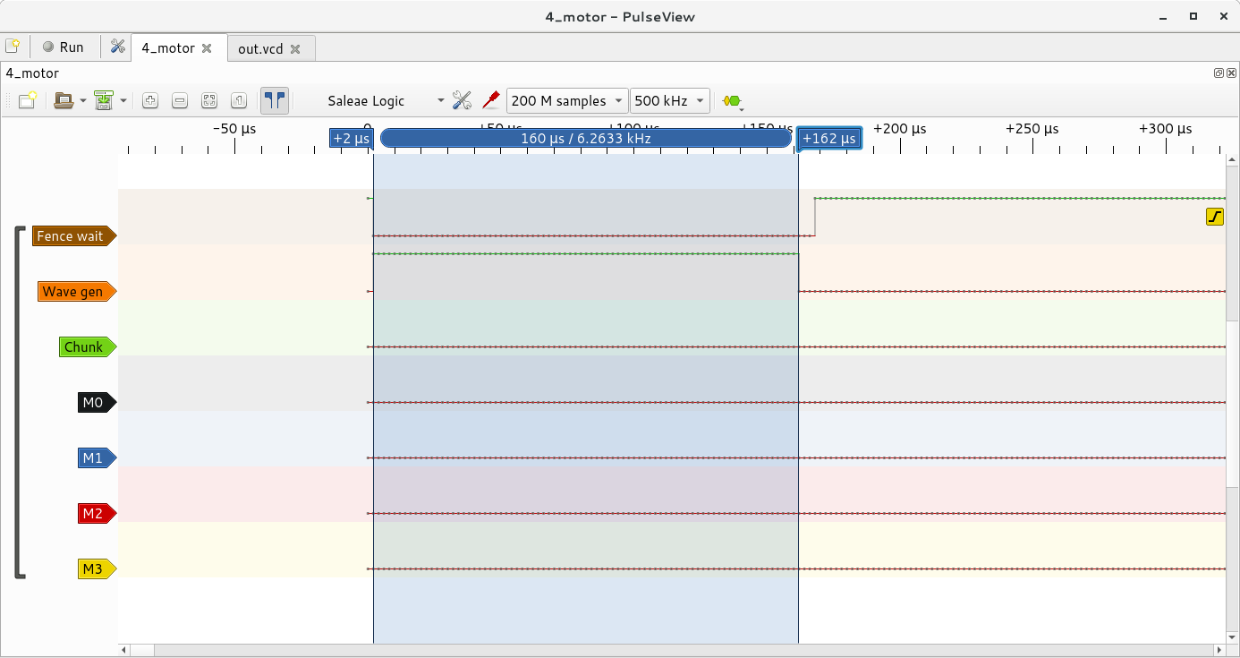
Wave calculation time
OK, so we get woken up to generate the next chunk - how long does actually calculating the next chunk take?
I'm using the stepper profile generation algorithm described here: https://www.embedded.com/design/mcus-processors-and-socs/4006438/Generate-stepper-motor-speed-profiles-in-real-time.
With 4 motors, in the worst case , we might need to calculate 4 sqrt() operations in a single wave_gen() invocation - if all 4 stepper motors have had their speed changed for this chunk. The only time I have that in my trace is the very first wave_gen().
This represents our worst-case calculation time, and is 160us on a Pi 3 B+.
The other case where wave_gen() could take a long time, is when all the waveforms are very high-frequency, meaning a lot of events are generated in that chunk. This is hard to get an exact number, but picking a section with all motors going fast, the wave_gen() time is 241us.
So, I think we can safely say that wave generation takes less than a millisecond - with the 5ms worst-case latency from scheduling, that means we have 10 milliseconds of idle time in every chunk.
Watching 'top' - with four motors a Pi 3 B+ uses somewhere between 1.5-5% CPU time on yapidh.
Testing backend
As well as being able to generate actual HW output from the Pi's GPIO, there's a "testing" backend in yapidh, which can be used to generate VCD files. VCD files are a common dump format from lab equipment such as logic analysers - and can be loaded by Pulseview (part of sigrok - the free logic analyser project).
This can be useful when you're debugging your event generators, as you don't need a real logic analyser to see if your event sources are working properly - just run yapidh, saving its output to a file, and view the file in Pulseview:
$ ./yapidh > out.vcd
^C
$ pulseview -c -I vcd -i out.vcd