 Rory
RoryDesign Criteria
- 100A continuous motor current
- Compact size for discrete mounting on an E-Bike
- Easy to solder
- Programable
- Waterproof
- Based on Benjamin Vedder’s VESC 4.12 hardware
Introduction
As part of my electric mountain bike project I needed a speed controller for a large hub motor.
I wanted the bike to be fast, so high current was essential. I had 3kW in mind at the beginning of the project (60A). I also wanted the bike to look good. Large speed controllers give an E-bike that bulky home-made look in my opinion. My speed controller needed to be small enough so that it could be hidden under the seat..
The controller would need to be fully programmable with safety features to avoid overheating the motor, over discharging the battery etc. These features are not available on the standard cheap controllers.
I found Benjamin Vedder’s VESC, (Vedder electronic speed controller) https://vesc-project.com/ which is very popular in electric skateboard projects. As such the hardware is designed to be compact rather than accommodate high current limits. The original design does not offer any way to easily heat sync the MOSFETs. The software is very advanced with associated windows and Linux setup applications. There are even android apps to monitor the device and adjust settings via Bluetooth.
I decided to re-design the hardware to allow for a current limit of 100A and above.
These were the first PCB’s I designed so although this project is currently working fine please suggest any improvements to my layout!
PCB Design
The original VESC 4.12 is a 4 layer board with components on both sides. The processor is a 64 pin STM32 which drives 6 MOSFETs via a DRV8302 MOSFET driver. The DRV8302 also contains a 5V switching regulator and 2 current shunt amplifiers.
My design reconfigures the hardware onto two, two layer, stacked boards to reduce the costs of manufacture. The components are mounted on the top side only to allow easy flow soldering using a hot plate or modified clothes iron.
The 6 power MOSFETs and current shunts are on the bottom driver board which is mounted onto a heat sink for cooling. The majority of the other components are on the top processor board. Splitting the boards like this was the best way to minimise the footprint of the device. Also, I expected to blow up a few MOSFETs during testing. The driver board as such is almost disposable with the expensive IC’s being positioned on the top driver board.
Note that I did not populate the servo connector. I didn't have a use for this input.
Version R1 – Now Revised
These were the first PCB’s I designed and as such there were a few issues. Some are quite embarrassing, but I will mention them all in the hope that you can learn from my mistakes.
Driver Board
- All MOSFETs were connected the wrong way around with the drain and source connections swapped. When getting to grips with DesignSpark PCB I was messing around creating symbols and PCB foot prints. I made the MOSFET symbol as an experiment but never checked it. Always check all symbols and foot prints down the most obvious details!
Processor Board
- Not enough border around JST connectors meant they didn’t fit. I was able to trim them down to allow me to test the board. Again, check symbols and footprints.
- Some passive components I had selected were actually very difficult/expensive to obtain. Make sure you can get the part before putting it into your design.
- The USB connector I had selected didn’t seem to exist anymore. I found one that was close enough to test. As above.
Although the issues above were frustrating I was able to modify things to get the firmware loaded into the STM32 and check that all the functions worked correctly. In fact, although I have since revised the driver and processor boards I am currently using a R2 driver board connected to my original R1 processor board. It’s not pretty, but I was trying to get the E-Bike finished quicky for a deadline. I couldn’t accommodate the cost of wasted components the the time.
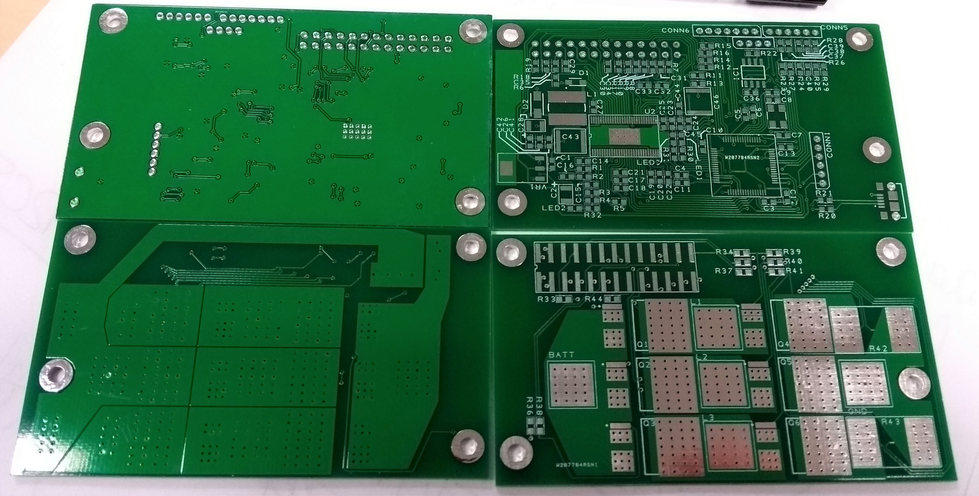 |
| Above: R1 PCBs. Processor board top, diver board bottom. |
Version R2 – Current Version
Driver Board
- Issues with R1 corrected.
- Tested and working correctly
Processor Board
- Issues with R1 corrected
- Currently un-tested. Still using R1 version
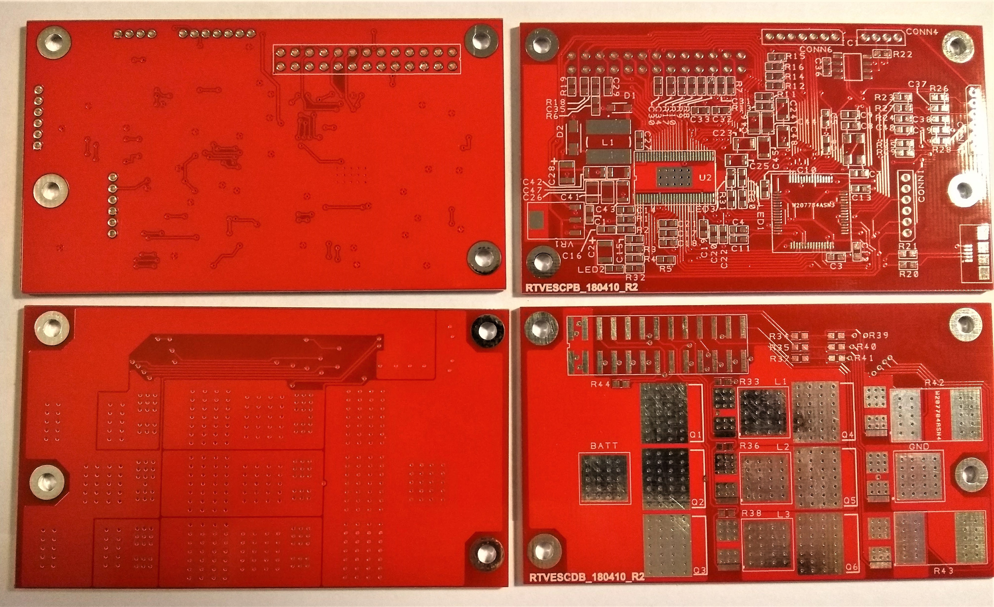 |
| Above: R2 PCBs. Processor board top, diver board bottom. |
The BOM is almost identical to the VESC 4.12 with the following exceptions:
- MOSFETs changed to IRLS3036-7PPBF due to a higher drain current.
- Current shunts were changed to CSS2H-5930K-1L00F due to higher power rating.
- USB and some passives changed to packages that were more easily available
PCB Manufacture
I had the boards made by PCBWay. 10 of each board with DHL shipping totalled $35. The boards arrived 7 days after I placed my order. The quality seemed very good, amazing value. They didn’t pay me to write this!
Soldering the Boards
I flow soldered the boards using a clothes iron. The clothes iron was modified to remove the end stop from the thermostat to allow a higher temperature to be set. This worked well, and I still use it to iron my clothes. I would recommend a through alcohol wipe before ironing your Sunday best though!
The trick is to use a very small amount of solder on each pad.
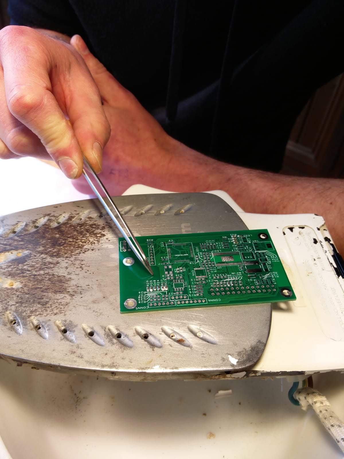 | 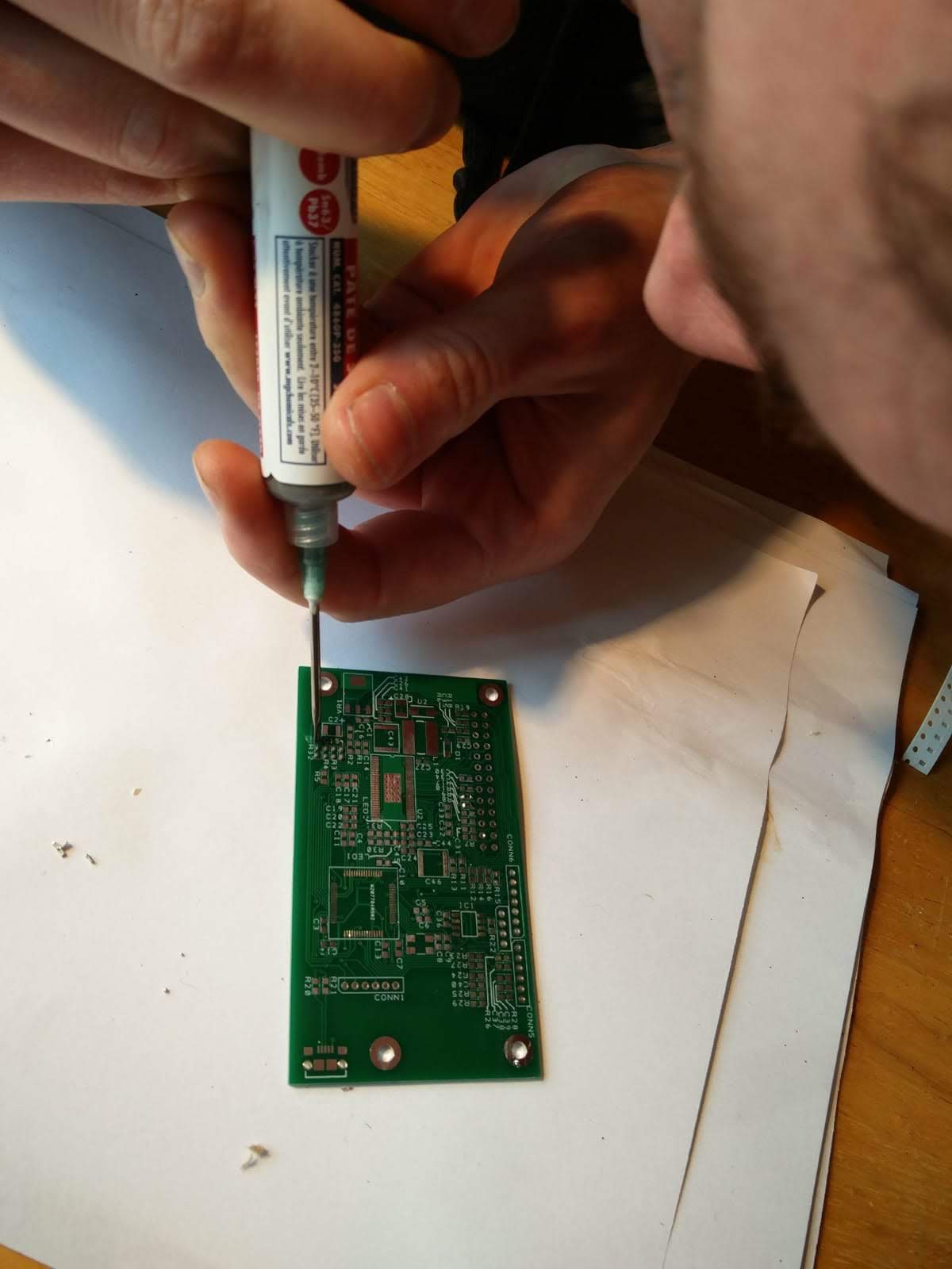 |
| I didnt take many photos of the soldering process in the 'heat of the moment'. Above Left: a test of a few 0603 restors Above Right: Solder paste applied by syringe. You need less than you would think. Right: Morphy Richards Turbosteam '++' with unlimited temperature set point! |  |
Enclosure & Heat Sink
I originally intended to weld up a custom aluminium case however I pay by the day to access a workshop with a TIG welder and I didn’t have time after finishing my E-Bike. It wouldn’t be another week until I could get back to the workshop. With a looming deadline I had to get something off the shelf.
My local (but not so local) high street electronics shop Cricklewood Electronics, the only one left in London, stock most sizes of the Hammond die-cast aluminium project boxes. https://www.cricklewoodelectronics.com/
I was stuck between a Hammond 1550D 114x65x51, which was larger than needed, or a 1550B 114x65x21 which was almost perfect but a little too small to fit the large electrolytic decoupling caps. I decided to go for the smaller option and mount the caps to the power cable outside of the case.
Cables are brought into the case via IP68 cable stuffing glands; 4 x M10 for the main battery cables, throttle cable and motor temperature sensor. The hub motor cable (which contains the phase and the hall effect sensor wires) enters via a M16 gland. These fit the enclosure nicely.
 |
| Above: Cables glanded into enclosure. Got a bit carried away riding on a beach hence salt-water corrosion on lid. |
The lid locating lip requires trimming to fit over the processor board JST connectors. This could have been avoided by locating the PCBs more carefully. The lid is sealed with silicone mastic.
The speed controller is mounted below the seat fully exposed to spray and dirt from the back tyre. After a few wet rides there has not been any signs of water ingress.
The enclosure is fitted with a 100x60x10mm heat sink. This probably wasn’t required. So far, the speed controller temperature never exceeds 10°C above ambient at a 60A current limit.
 |
Testing and Operation in Use
Once the initial PCB layout issues were corrected I was able to easily setup the motor and throttle input using Benajmin Vedder’s VESCTOOL available from https://vesc-project.com/vesc_tool.
The bootloader was downloaded using an STLinkV2 clone.
I am running a large 1.5kW hub motor in FOC mode from a hall effect throttle on a 12 cell lithium battery.
Everything was running perfectly for 10 minutes until the motor cut out and ‘FAULT_CODE_DRV8302’ was displayed via VESCTOOL. I discovered that gate capacitance of the new MOSFETs was too high for the DRV8302 to run at a 20KHz PWM frequency which is the VESC default. The DRV8302 had overheated and been damaged. Always read the datasheet! I replaced the DRV8302 and monitored its temperature via a surface mount thermistor soldered to the back of the board beneath the IC’s power pad. This was monitored using the VESC’s motor temperature input. At 20kHz PWM frequency I saw the temperature climb quickly. I reduced the frequency to 16kHz where the temperature stabilised to around 40°C. More effective heat sinking of the DRV8302 would negate this issue.
I am running the ACKMANIAC-ESC Monitor android app on my phone which is communicating with the speed controller via a HM-10 Bluetooth low energy module installed inside the metal case. Surprisingly there are no issues with RF communication through the case.
 |
| Above: HM-10 BLE module for communication to android app. |
I have been running the speed controller with a 60A current limit for a few hundred miles and I have never seen the temperature exceed 10°C above ambient at this power level.
I was reluctant to raise the power level any higher until recently because I was afraid about snapping the drive chain or bending something. I could already feel the bike frame flexing slightly with 60A. Today I boldly decided up the current limit to 100A. This was not totally successful. The DRV8302 seems to be going into overcurrent lockout and cutting power. The current limit function of the DRV8302 should already be disabled. Further investigation here is required.
Conclusion
I am very happy with the outcome of this project. Particularly as I had never designed a PCB or attempted surface mount soldering before. I would encourage you to have a go, its not as hard as it looks!
The speed controller has run for a few hundred miles at a current limit of 60A with no issues whatsoever.
Further investigation is required to raise the current limit past 70A.
It would be nice to re-design the controller to accommodate supply voltages above 50V. Currently this is limited by the DRV8302 MOSFET driver.
I have some spare boards, message me if you want some.
If you build you own don’t forget to lower the PWM frequency to 16kHz. Let me know how you get on!
Many thanks to Benjamin Vedder for his excellent original design and comprehensive software. https://vesc-project.com/