This project has been mostly on hold for a while. Not because of an issue, but because the previous SOL version was operating well outside in Northern Michigan for about 9 months between August 2019 to April 2020. In April, I started noticing some issues. SOL was still sending data to our server as normal, but the power measurements looked very wrong and the battery had stopped charging. Upon inspection, water had gotten inside the case and caused corrosion. Specifically, the wires to the solar panel had broken, causing the issues. I tried to fix it, but the damage was done.
Water ingress was always a concern. I had used an IP rated waterproof enclosure, but I had drilled holes for the LED indicator light, solar panel wires, and capacitive touch button. All were "sealed" with adhesives and/or gaskets, but it was still a known weakpoint. In addition, the capacitive touch button was always an issue. I had a lot of trouble tuning the settings to be appropriately responsive while not triggering false positives all the time. It also added a step in assembly which took time to build.
With these known issues, I made a design update.
The new version was meant to again use an IP-rated enclosure, but this time I would drill no holes in it. For this to work, the solar panel must be inside the enclosure, and therefore the enclosure must be transparent. This does raise the question of how much light is absorbed or reflected from the transparent cover. I do not yet know the answer to that. Because the cover is clear, PCB mounted LEDs can be used to indicate modes. Finally, instead of a capacitive touch button used to enter configuration mode, I used a LIS3DH low power accelerometer in "wake-on-shake" mode. This accelerometer can monitor acceleration at 10Hz while consuming 3-4uA, and will wake up the ESP32 on a shaking event. Therefore, the user can give SOL a quick shake to enter configuration mode. In testing this is very easy and reliable. The addition of an accelerometer also raises the possibility of sensing roll and pitch of the device to infer information about roof angle.
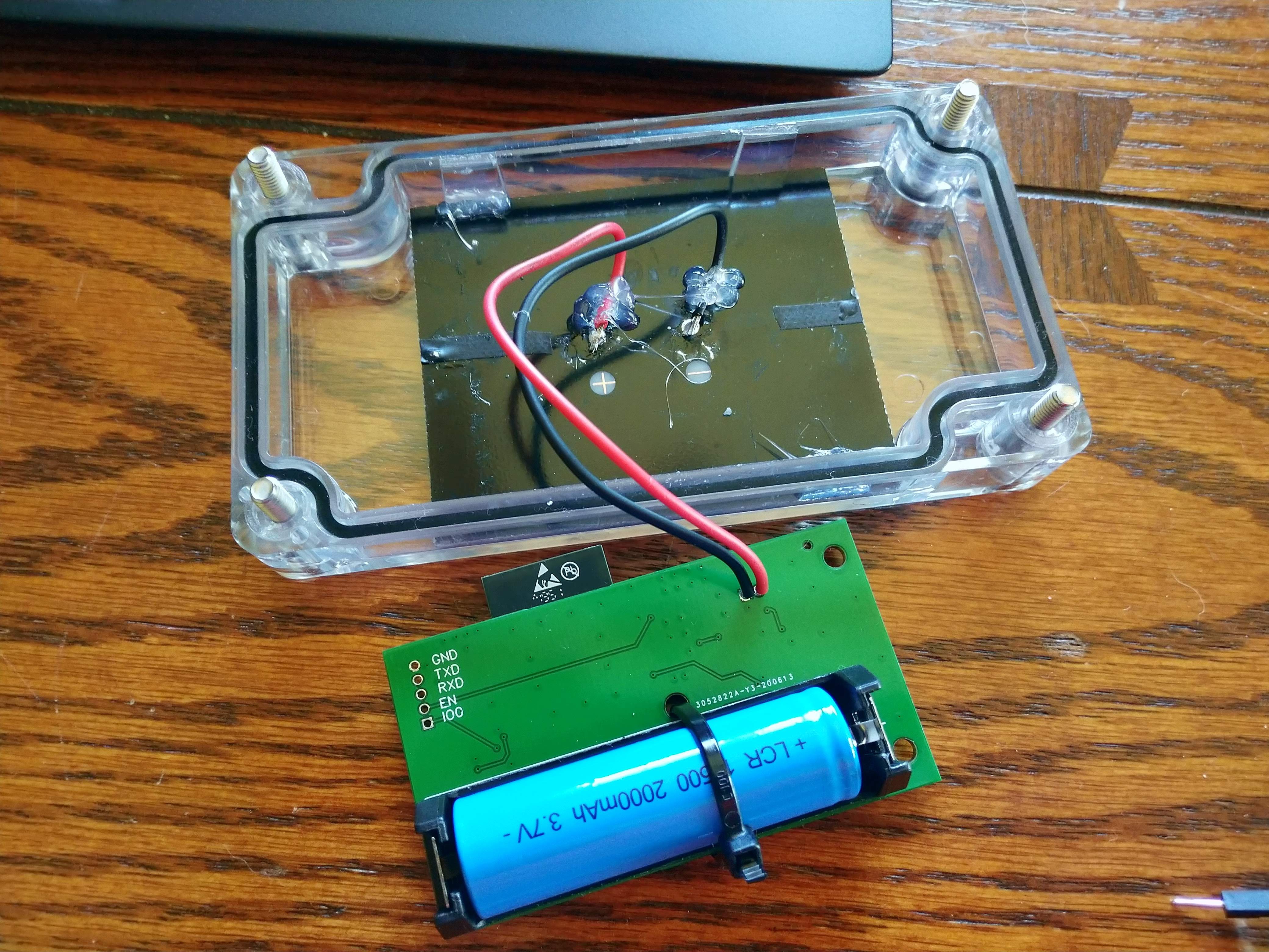
I used JLCPCB for the assembly. They assembled most of the parts except through-hole components and the ESP32 module itself. I did the rest. SOL is mounted in a Hammond Manufacturing polycarbonate enclosure with transparent lid. The solar panel is a perfect fit into the lid, with a bit of hot glue added to hold it in place. The picture below shows SOL assembled and connected to the solar panel.
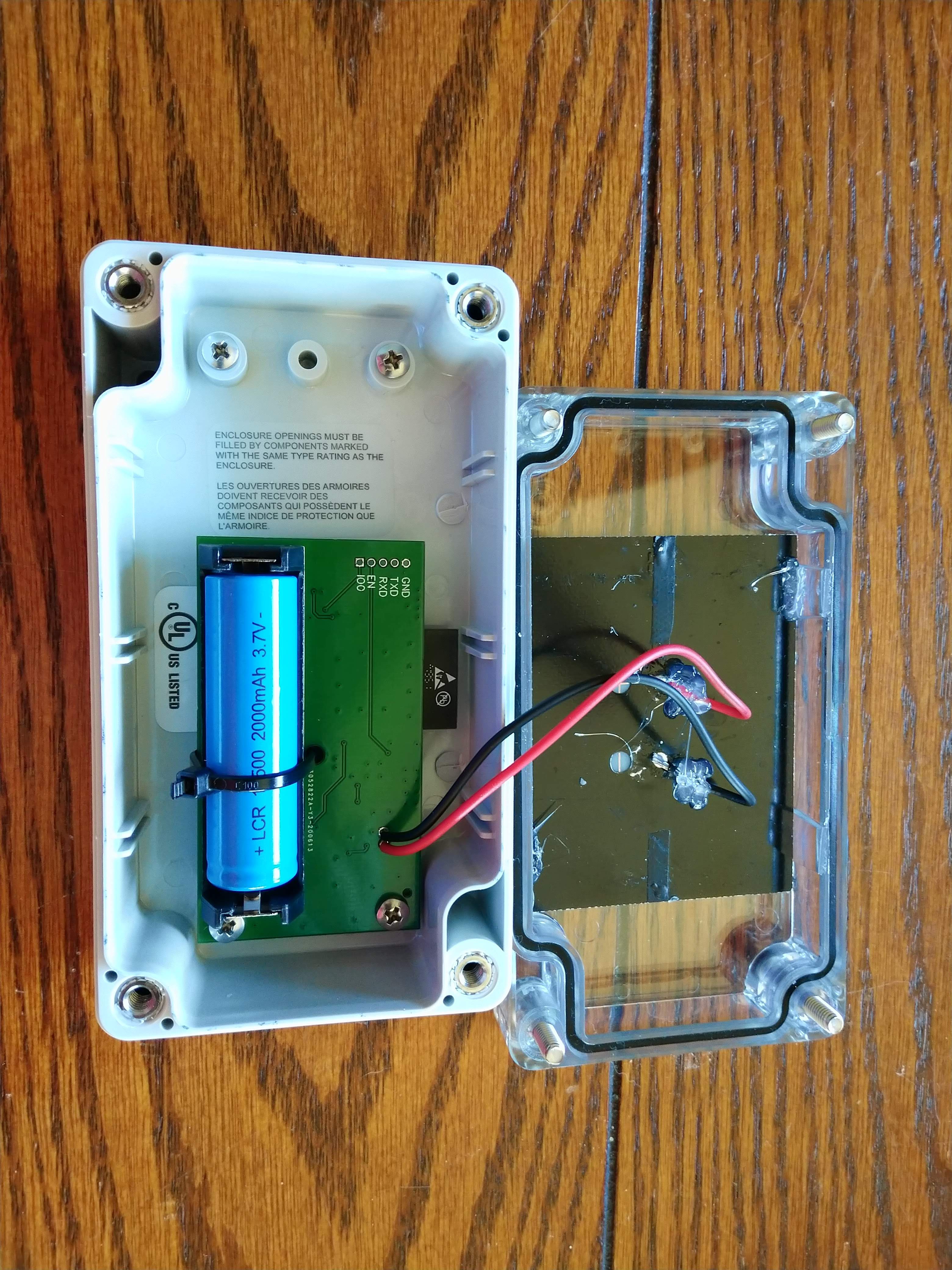
The PCB then mounts into the enclosure as shown below. Unlike the previous enclosure which had a cut-to-fit gasket, which always had a seam, this enclosure has a one-piece gasket for a (presumed) better seal.
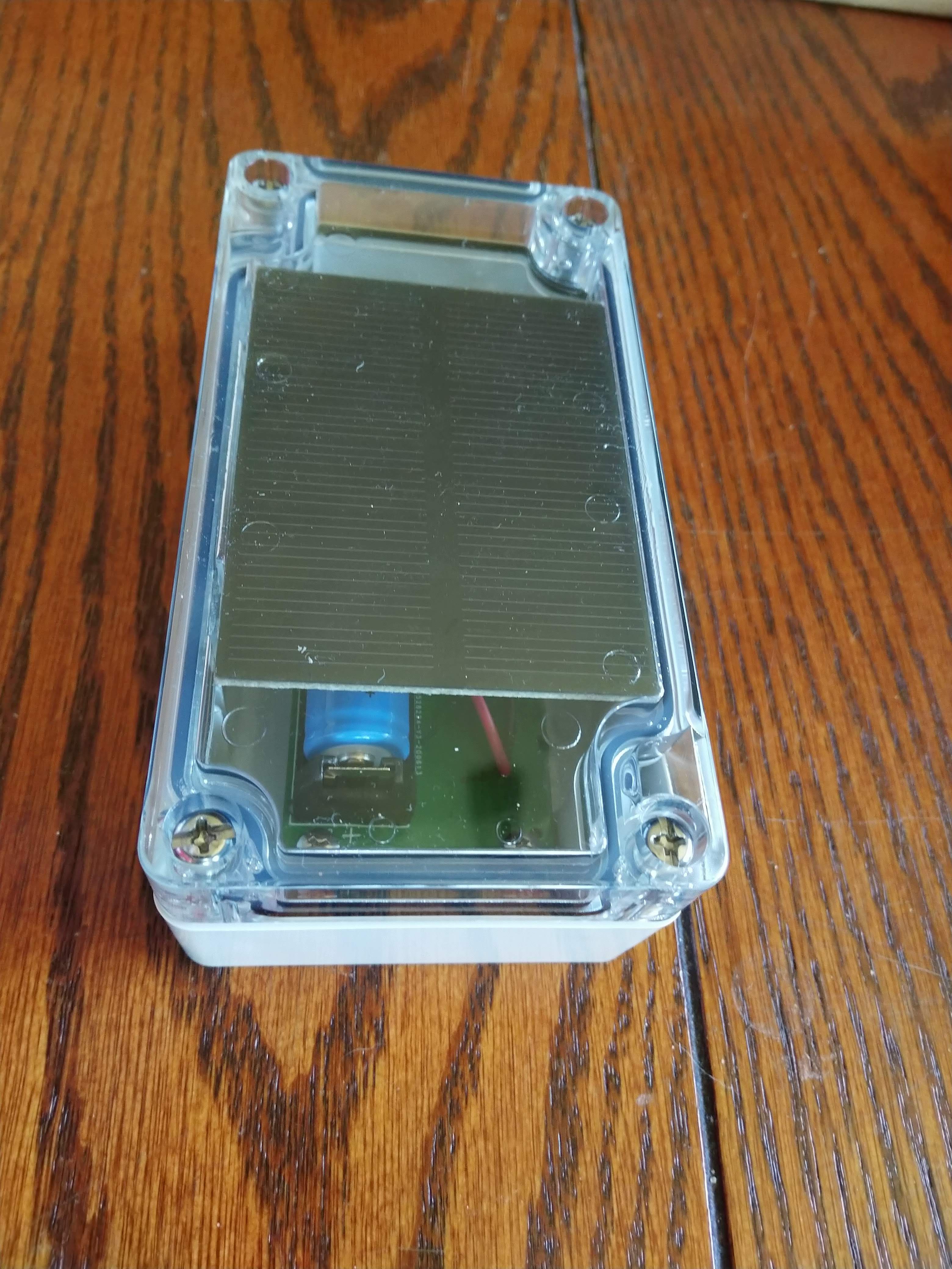
Fully assembled, the system looks like below. The PCB and battery are now exposed to direct sunlight, so there is some potential concern of UV degradation.
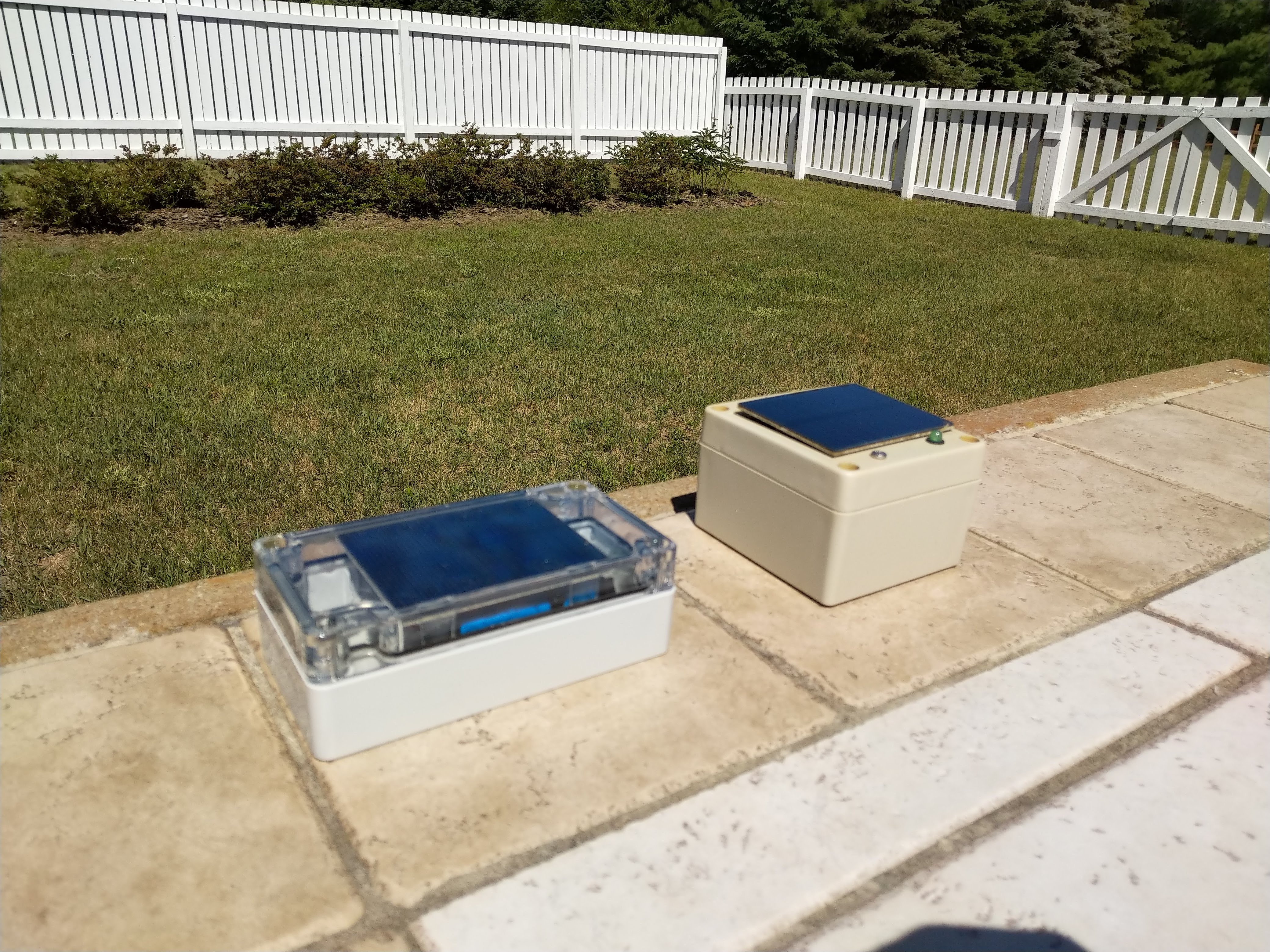
Finally, the image below shows this new version outside next to the old version.
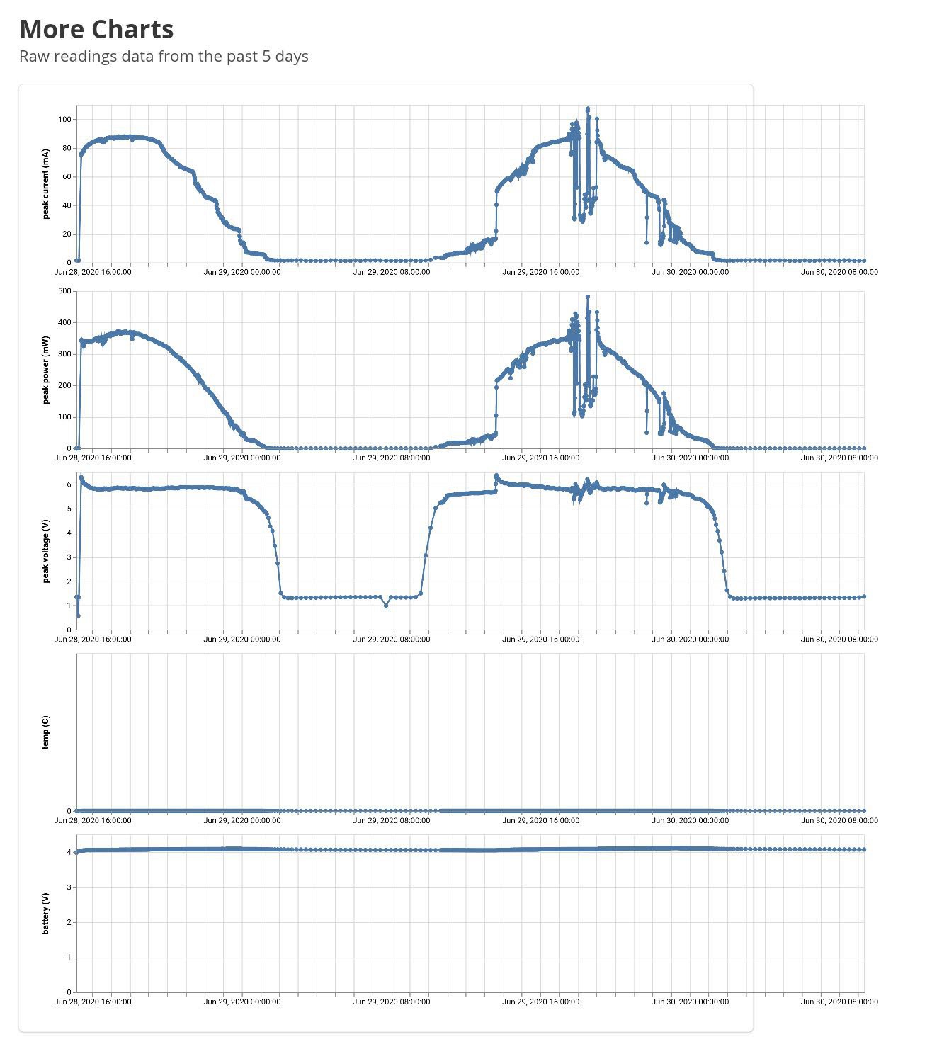
The data is coming in to our server. After 2 days, the data mostly looks good. There are a few issues though. The temperature always shows 0C. The LIS3DH accelerometer contains a temperature sensor that I had planned to use. However, it appears that sensor is only useful for relative measurements and must be calibrated carefully. I do not want the added hassle of calibration when that sensor is mainly for approximate measurements to disable charging outside of acceptable conditions. Also, during nighttime, the system is reading nonzero solar panel voltage of about 1.3V. It is not clear if this is a bug, or if the bright moon or house lights are causing this. This solar panel will produce a nonzero voltage with very little light, although there will be effectively zero power available.
This new version also has a different charging setup. The previous version had a very simple voltage regulator to 4.2V, then a Schottky diode to the battery. It was current limited by nature due to the limited current available from the solar panel, but was nominally a constant voltage trickle-charger. It worked well, but by design would only charge the battery to about 4.0V. The new version uses more standard charging electronics. There are a few challenges with this:
- Many single cell Li-ion charger ICs are meant for USB charging and max out at 6V input, which is too low.
- I need the ability to disable charging when using the solar panel as a sensor.
- Many single cell Li-ion charge ICs are meant for faster charging. If I set the current limit too high, it will only charge very occasionally. A trickle charge setup is best.
To account for these, I used an IC with an enable pin controlled by the ESP32. A 5V regulator regulates panel voltage down to an acceptable range. Finally, I set the current limit as low as possible, at 50mA. This system is charging. It began at just under 4V, and is now up to 4.07V. It has been very sunny however, and it remains to be seen if this system will trickle charge in more cloudy conditions.
Discussions
Become a Hackaday.io Member
Create an account to leave a comment. Already have an account? Log In.