 Brian Barrett
The screws are a little bit interesting and also a big pain. First, here is drawing of the screw in question.
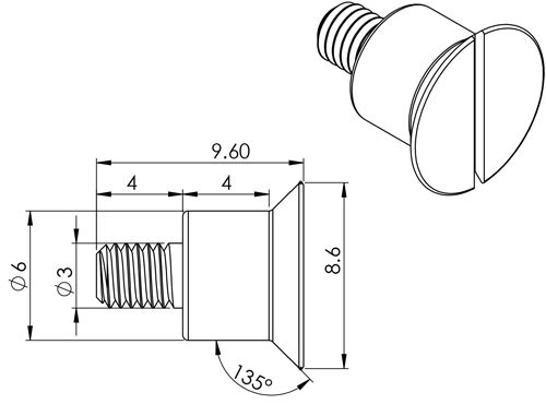
The screw is a spacer and a flat head screw all in one. I had these CNC machined and not made with custom tooling. The only impact this had was on the head of the screw. By necessity they slot was saw cut. This meant that if I made it philips head, the slots would be cut to the edge. I made the decision to go with a slot head and this looked for authentic. The philips would have looked odd with the cuts extending to the edge of the screw. Given my choice, I would have made them hex, but I just didn't feel like making tooling or using EDM machining for 100 screws. As it turns out, I got them all as a freebie from a supplier.
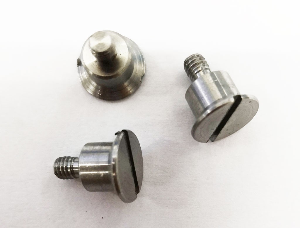
Since high end clocks and watches use slot head screws, I didn't feel this change would affect the quality look of the product. This was the only change I made to the design files.
I don't like these screws because there is a flaw in the design. The screws serve 2 purposes and due to tolerances it's almost impossible to do both perfectly. We need to look at the internal structure of the keyboard to see the issue.
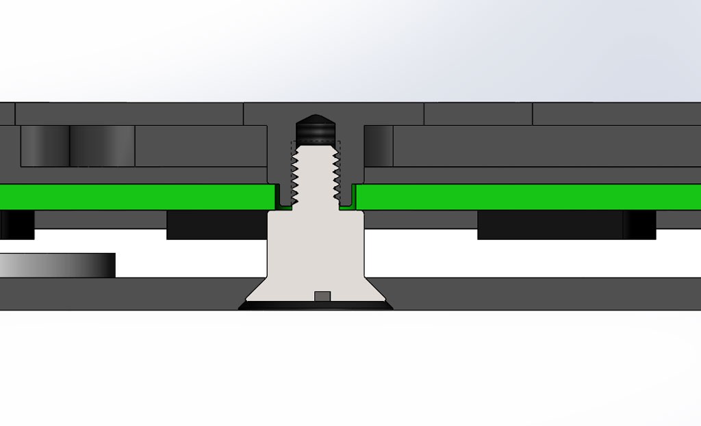
I've made the top and bottom of the case dark gray. The white in between is the acrylic layer with the screw being the center of the image. The screw should both clamp the PCB (green) in place and hold on the back cover which also serves to clamp the acrylic in place. The back cover is fairly thin and would bend if you tighten the screws too much. For the screw to clamp the PCB and hold the back cover in place without bending it requires the length to be exact. The problem is that the PCB material has a +/- 0.1mm tolerance on it. Not to mention the machining tolerances on the screws, aluminum and acrylic. To add to the issue, if the screws aren't tight enough, the back cover can move slightly as it has no other alignment features. The acrylic has pins that stop is sliding but not the back cover. The best compromise is to have the screw boss short so it doesn't quite clamp the PCB. Once the 87 switches are installed, the PCB can't move anyway, but when they aren't installed, the PCB can move 0.1mm or so. Not a big deal, but it would have been better to have internal screws for the PCB and external ones for the cover. The PCB has alignment pins, so it can't move side to side, only up and down. 0.1mm is almost nothing and as I said once assembled, it's a non issue. I still don't like the dual purpose screws and with tolerance stack up, I see no way to do a production run without this issue.
Discussions
Become a Hackaday.io Member
Create an account to leave a comment. Already have an account? Log In.
The screws came over a week ago, but again I'm a bit behind with my log.
Are you sure? yes | no