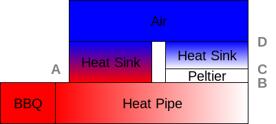
To generate power with a Peltier device, you need to apply a thermal differential across the device. You need to make one side hot and one side cold like this:

The BBQ is much hotter than the air, so generating a differential is not difficult. The difficulty comes in trying to manage the extreme temperatures of the BBQ. Lets take a closer look at the elements of the thermal circuit:

Point A is contacting the BBQ, which could be several hundred degrees Celsius. The air in the vicinity of the BBQ could be a little higher than typical room temperature, the standard commercial temperature range of 0 to 70 degrees Celsius is probably a reasonable approximation for point D. Points B and C are the interfaces to the Peltier device. The TEC1-12706 like this one ( http://peltiermodules.com/peltier.datasheet/TEC1-12706.pdf ) is rated for a maximum temperature of 138 degrees Celsius, so the biggest challenge will be dissipating enough heat from the BBQ before it reaches the Peltier device. A common heatsink like 655-53AB from Wakefield should be sufficient for the cold side. For the hot side we will need some sort of heat pipe. Since we want to dissipate heat before it gets to the Peltier, we actually do not want a high performance heat pipe and a simple slab of metal, like aluminium should fit the bill. To ensure that enough heat is removed before the Peltier, we can add another heatsink on the heat pipe between the heat source and the Peltier. This will take some trial and error to determine the right amount of heat to remove (it would probably be a lot quicker in a thermal simulation tool, but I don't have access to that, and it sort of takes the fun out of it anyway). The basic thermal circuit I envision is something like this:

I am concerned with the wide variation of temperatures we could see from the BBQ. The max temperature is quite high, but I also want it to turn on quickly, so I need it to start working at lower temperatures. If only there was a way to actively adapt the thermal circuit as the temperature rises...
Adaptive Thermal Circuit
If you look at the datasheet for the Wakefield 655-53AB, one thing that you will notice is that the effectiveness of the thermal transfer is very dependent on the airflow across the device. WIth natural convection, there is a much larger temperature differential between the air and the hot side, than there is when air is forced through the fins. When the temperature starts rising, we will see a higher voltage across the Peltier device, we can use this voltage rise to turn on a fan to force air through the fins and remove more heat from the heat pipe. Thanks to the popularity of drones, there are some very cost effective, small, low power motors readily available. Fortunately when the voltage rises, it also means we have extra energy available to power the fan. If we happen to cool it too much, the voltage will drop so it should self regulate, but we should tune the gain to avoid listening to the fan cycle too often.
 greg
greg
Discussions
Become a Hackaday.io Member
Create an account to leave a comment. Already have an account? Log In.