 Al Williams
You might wonder why we are building a half adder and what other kinds of adders there are. A half adder takes two bits in and produces two output bits, a sum and a carry:
| A | B | Sum | Carry |
| 0 | 0 | 0 | 0 |
| 0 | 1 | 1 | 0 |
| 1 | 0 | 1 | 0 |
| 1 | 1 | 0 | 1 |
This is suitable for adding the first two bits of a multibit word. The reason you can't use it on subsequent bits is because it lacks an input for a carry bit from the previous stage. You really need a 3-bit adder. One that takes the two input bits and the carry from the previous bit. That's a full adder:
| A | B | Carry In (C) | Sum | Carry Out |
| 0 | 0 | 0 | 0 | 0 |
| 0 | 0 | 1 | 1 | 0 |
| 0 | 1 | 0 | 1 | 0 |
| 0 | 1 | 1 | 0 | 1 |
| 1 | 0 | 0 | 1 | 0 |
| 1 | 0 | 1 | 0 | 1 |
| 1 | 1 | 0 | 0 | 1 |
| 1 | 1 | 1 | 1 | 1 |
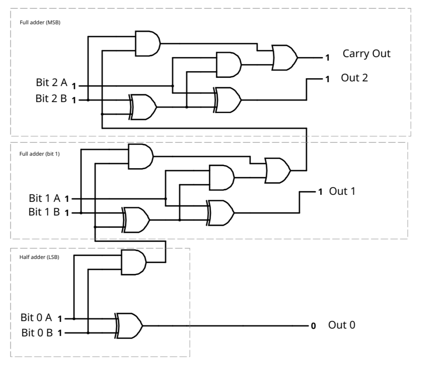
The full adder is almost -- but not quite -- two half adders. Typically, for a full adder you'll need two two-input XOR gates. One computes B+C and the other takes that sum and adds A to produce the final sum. There are several ways to compute the carry, but one way to do it is to realize that the carry out is true in two cases. The first is when A is 1 and B+C (that is, the sum from the first XOR gate) is also 1. That covers the rows above where A=1, B=0, C=1 and A=1, B=1, C=0. That leaves two rows uncovered: A=0, B=1, C=1 and A=1, B=1, C=1. If you think about it, the A must be a don't care because it can be either a 1 or a 0. So the second case is B=1 and C=1.
You can easily implement this with two AND gates and an OR gate. The schematic appears below and if you click the link you can try it in the excellent Falstad simulator (just click on the left side 1s and 0s to set the input you like). The bottom half adder handles the least significant bit (LSB). The carry output goes to the full adder for bit 1 through the carry input. That adder's carry output goes to the most significant bit (MSB) full adder.
You could implement this in Verilog for practice using gates, but in reality, Verilog will figure this out for you when you write something like:
module fulladder(output carryout, output [2:0] sum,
                 input [2:0] a, input [2:0] b);

  assign {carryout, sum} = a+b;
  endmodule
Not only is this easier, but the FPGA tools will probably identify how to do this using parts of the FPGA specifically meant for things like carry propagation, allowing you to possibly get higher density and speeds than if you just specified things at a gate level. You can experiment with that in the simulator, if you like.
Discussions
Become a Hackaday.io Member
Create an account to leave a comment. Already have an account? Log In.