 Dylan Brophy
Normal voltage requirement is 2v, switches at about 600mV. All transistor betas are 100.
The capacitors are for simularing parasitic capacitance.
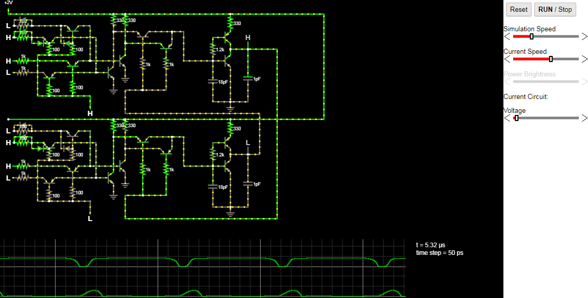
The above circuit is two LUTs connected to make a clock. One is configured as a buffer, the other as an inverter. The 8 inputs on the left tell the LUT what values are where. The inputs on the bottom of the LUTs are the address. The image above is at two volts input power.
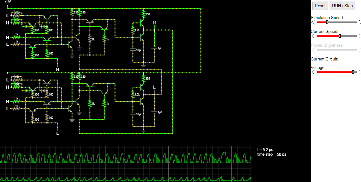
The circuit can take voltages up to about 11v before the logic stops working. This is at 11V to see how it switches right before the voltage that it stops working (between 11v and 11.16v). there is a lot of ringing for some reason, probably due to the small capacitors to simulate parasitic capacitance.
Discussions
Become a Hackaday.io Member
Create an account to leave a comment. Already have an account? Log In.