 Frederic L
It turns out the schematic from previous log contains around 200 wires, that is, for one display. I have neither the patience to cut to length and strip 400 wires nor do I have enough breadboards to accommodate for all the ICs in order to run my two displays.
So, for the price of extra breadboards and wires, I can have a PCB manufactured, which not only will eliminate (or at least reduce) the risks of mis-wiring, but also will keep the “lab” (read: my living room) tidy. The only downside is that I loose the flexibility of changing the circuit on the go, but I worked hard on the schematic (even harder on the PCB layout) and I believe it should work.
The PCB size is based on the available ANNAX mounting holes and should fit nicely on its back with a few spacers. I chose only through holes components for ease of soldering as well as for ease of changing burnt ICs (plan for the worse, hope for the best). The ones most susceptible to get grilled are the source and sink drivers, so I’ll mount those on sockets.
Having through-hole components all over the board, and trying to keep them all on the same side (reducing overall thickness) was a real challenge as it restricts the available space for routing, but I managed to make it work, hopefully without breaking too many laws of good PCB design (eg. the GND plane on the back has more signal lines cutting through it than I would have liked).
The PCBs have been ordered from JLCPCB. I have used a few time past and I was pleased with the results. Five boards for 16€, one week delivery for 24€, for a total cost of 40€ (standard delivery was 12€ only but I'm in a rush to get started).
Here are some screenshots of the layout, I took the liberty to make some silkscreen “art” on the back but the result might not be as expected as there are vias and through-hole pads literally everywhere.

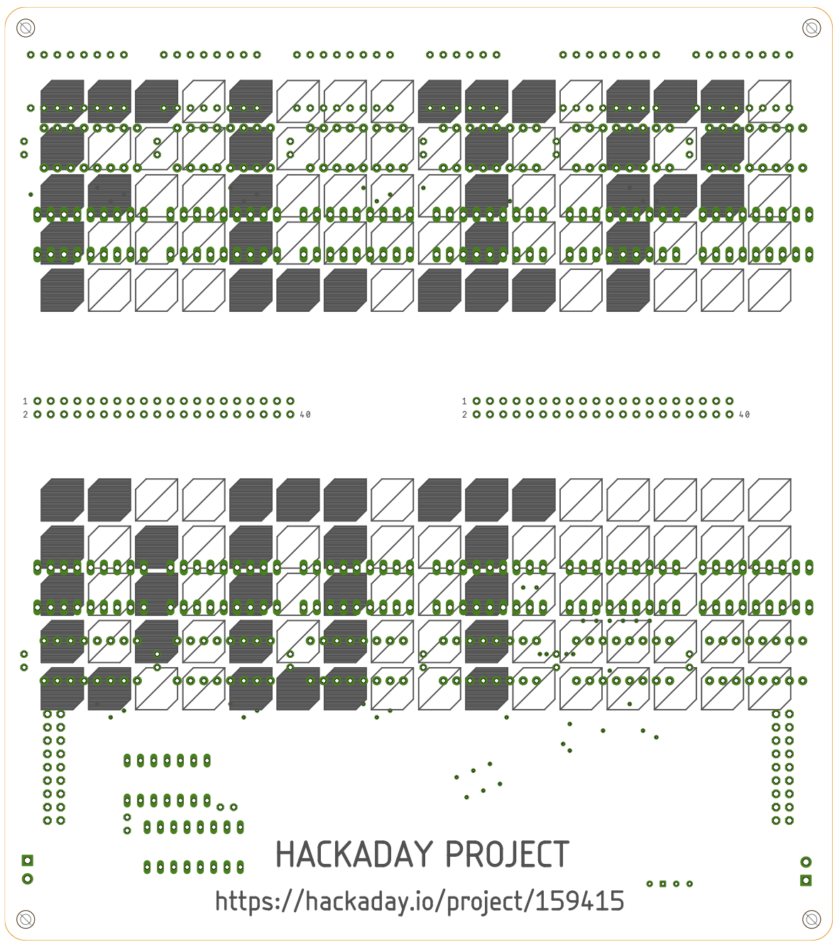
On the final board, at a later stage, I’ll probably use SMD components to have more space to integrate an appropriate voltage regulator, some level shifting chips, and the ESP32. Maybe a nice soldermask color, and higher quality surface finish, would make for a cleaner, all in one final product, ready to be framed !
Discussions
Become a Hackaday.io Member
Create an account to leave a comment. Already have an account? Log In.