 Chris Graham
While waiting for a milled mouthpiece prototype to arrive from Protolabs (hopefully the final perfect version), and for the epoxy to dry on my other mouthpiece, I decided to design and order three different small PCBs that will be useful for future testing.
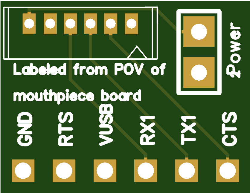
The following board is an adapter to take a cable from the Picoblade serial port (finger unit) connector on the main board and convert it to 0.1" spacing for testing and for prototyping finger units. It's also also compatible with the FTDI USB to serial TTL adapter smart cable for testing the serial protocol communicating with a host computer. The jumper is to optionally connect the power lines.
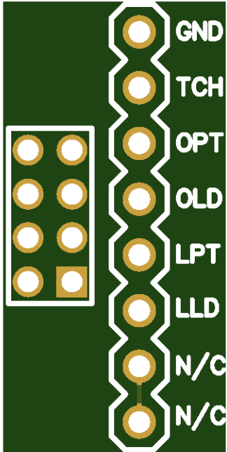
This board is an adapter to take a ribbon cable from the pins on the small mouthpiece connector board header and convert to a row of 0.1" spacing pins for use on a breadboard. This board may also be useful if anyone wants to use the mouthpiece with their own electronics, not the Multiwind main board. The connections are ground, the upper lip touch pad, the oral cavity phototransistor, the oral cavity LED, the lower lip phototransistor, and the lower lip LED. The other two pins are not currently used in the mouthpiece but are included for future options.
I also designed a little board is to test an idea for making touch pads to be finger unit instrument keys. The following images shows the concept. This is is a very preliminary design for the finger unit of a brass style instrument. I won't take time for now to explain all the details now but it would have fingering somewhat similar to the EVI.
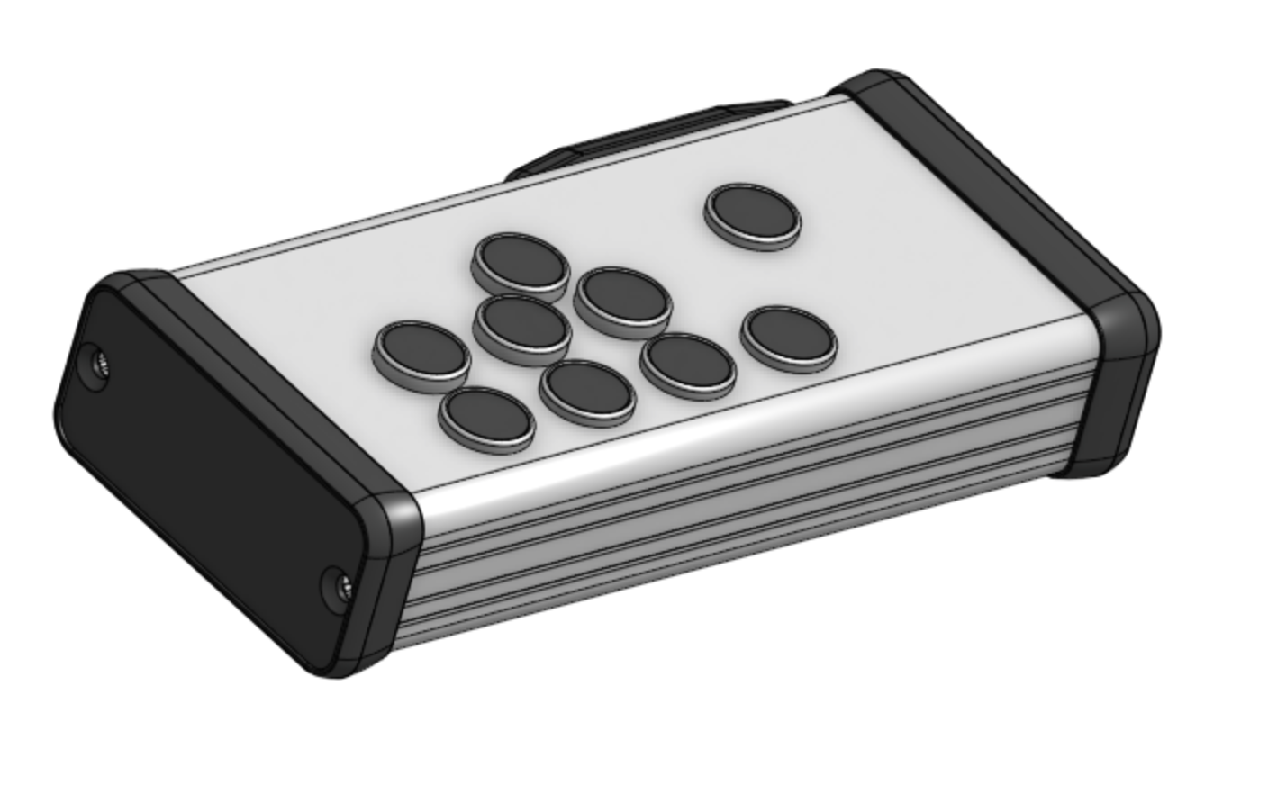
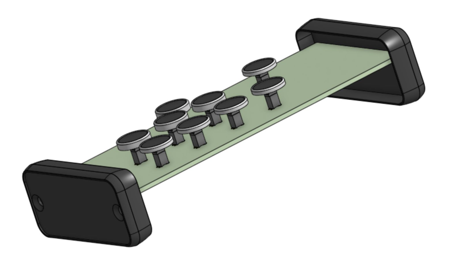
The following is an view with the housing removed. It's not shown but every finger unit would have a processor, probably a Teensy 3.2 or LC. It could be mounted on the bottom of the board shown here or on another board that would slide in one level below the one seen here.
You can see capacitive touch keys plugged into the top of the PCB.
I needed a way to be able to connect and attach the keys into the unit after the PCB was slid from the end into the aluminum housing. I also wanted to avoid having to run individual wires to each key pad and bulky connectors.
Note that on the underside of a board below this one there might be headers facing downward with keys inserted from the bottom of the housing.
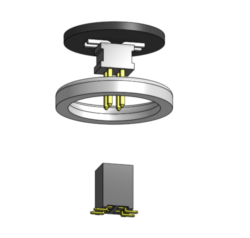
The following is an exploded view of a single key. The pad itself is a round two layer printed circuit board 10mm in diameter and 0.8mm thick. Soldered to the bottom is a four pin 0.127 inch spacing surface mount header. The ring is a bezel. Many of these could be 3D printed very quickly to any desired shape. It covers the edge of the board and to insulates it from the aluminum housing. The pad PCB snaps into the top of the bezel.
The male header and its pins are inserted though a 1/4 inch hole in the housing and plug into a female header on the main board. The entire top of the round PCB pad is a copper layer over-painted during board manufacture with some colour. In this case it's black but PCBs can be ordered in other colours such as white, red, yellow and green. This would permit making key pads in different colours maybe for coding or just to look cool. It will be cheap to make even hundreds of these boards. The heads are also inexpensive. The total materials cost of a key could be under $2.50 and connecting it is free other than making the main board.
A one-pin header would have been sufficient as there only one electrical connection to pad but I chose a four pin header for these reasons:
- I'm hoping that the friction of the pins will be enough to hold a key in place. There will be more friction from four pins.
- In some cases it will be desirable to have non circular keys (e.g. a narrow key next to another key or an elongated key along the edge of the housing. Having multiple pins would prevent key rotation. For a very long key it may even be desirable to have to attach to the main boad with two headers through two 1/4 inch holes.
- It's much easier to obtain the four pin headers.
- Having more pins may permit segmenting the pad to allow touch sensing different parts of a key.
A final advantage of this plan for attaching keys is that it should be easy to try different arrangements. It's quick and inexpensive to create and order a PCB with a different pattern for the headers.
Regarding drilling the holes through the housing, for now I'm 3D printing templates with little holes to allow marking hole positions. For larger quantities Hammond offers manufacturing of custom milled and drilled housings in moderate quantities for a reasonable price.
Discussions
Become a Hackaday.io Member
Create an account to leave a comment. Already have an account? Log In.