 Dan Julio
Initially I connected the Lepton to a Raspberry Pi 3 and ran demos from the Group Gets repository. However many of those are written for the lower-resolution Lepton 2 family of modules. I hacked a couple of them with less-than-stellar results because of the much larger dataflow from the Lepton 3. I had more luck with Damien Walsh's leptonic but even it would occasionally lose sync on a lightly loaded Pi. This lead my decision to try to use the VSYNC output to make it easier to synchronize the VoSPI transfers to the Lepton's video engine.
FLIR has a reasonable set of default settings. For example the Lepton 3.5 is ready to output radiometric data (with absolute temperature values for each pixel) immediately after booting. However changing any of the default settings (e.g. enabling VSYNC) requires using the I2C interface to access its command interface (IDD). They provide a C++ library that is designed to compile on 32- or 64-bit Linux machines that I ended up porting to the Teensy Arduino environment. With this I was able to enable VSYNC and with the Teensy and Lepton on a proto board start to figure out how to reliably get video data out of it. It's a bit picky about the timing and data gets garbled if the host isn't able to keep up.
The Lepton 3 and 3.5 output data in 4 segments, each one quarter of a complete frame. The segment length may vary depending if the data is formatted as temperature or AGC-processed data or is 24-bit RGB colorized values or includes additional telemetry information. Each segment is comprised of a set of 60 (or more) 164-byte or 244-byte packets, including packets specifically designed to be discarded while the Lepton prepares the valid data and any optional telemetry data. Although the Lepton's internal frame rate is about 26.3 Hz because of government regulations it only outputs ~8.8 frames of video per second. However it generates data for all frames leading to a VSYNC rate of ~105.3 Hz (4 segments/frame). This means the host has to read, and process for validity, an entire segment after each VSYNC. It took me a while before I could manage this on the Teensy.
The host must resynchronize with the Lepton whenever it gets out of sync or it will receive only garbage data. This requires idling the VoSPI interface for at least 186 mSec. I found that it takes the Lepton a few VSYNC pulses to start outputting valid data. When the host is in sync then it will output 4 consecutive good segments on 4 consecutive VSYNC pulses every 12 VSYNC pulses. The other eight VSYNC pulses contain invalid segments (identified with a segment number of 0). Because my test fixture uses a single SPI interface to read data from the Lepton and then write frame buffer data to the LCD display the test sketches are only able to reach about half of the maximum frame rate (~4.4 frames/sec).
I put the ported IDD library and three test sketches into a github repository. The sketches also use the Adafruit ILI9341 and GFX libraries for the LCD module (although the code has its own routines to write pixel data to the display).
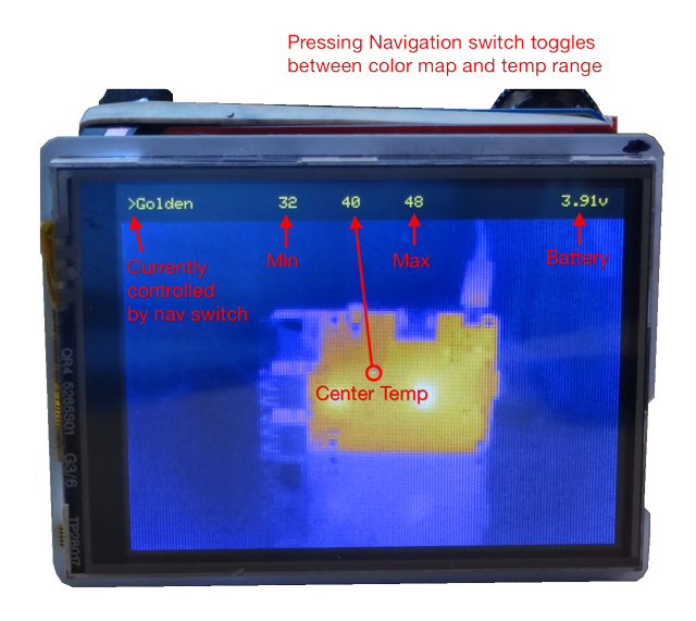
lep_test6 - This sketch takes the default 16-bit absolute temperature (Kelvin * 100) value of each pixel and linearly scales the data to 8-bit values that can be run through a color map look-up table for display. Because the data has absolute temperature values it is easy to display the temperature (currently without worrying about any real-world emissivity issues) of the center of the image. Normally the scaling maps the data from the minimum and maximum in the frame. However this sketch allows the user to select a few temperature ranges to scale the data in so the image does not change radically as different temperatures enter or exit the frame.
The Lepton also has a more sophisticated AGC capability that is claimed to produce better images than linear scaling. I spent a lot of time trying to figure out how to enable this function (ultimately I found I had to disable the radiometric calculations before the it would output AGC processed 8-bit values). I am still comparing the image quality but I wrote two additional sketches with AGC enabled.
lep_test5 - Enables AGC and takes the 8-bit output through color maps in the code for display.
lep_test7 - Enables AGC and 24-bit RGB output. The Lepton generates RGB data from one of its built-in color maps and this is read and converted to 16-bit RGB for the LCD display. Mainly I wanted to see if I could handle the additional data.
Future plans include attempting to interleave writing data to the LCD with reading it from the Lepton to improve the frame rate. I'd also like to see if I can include an emissivity calculation to make the temperature data more accurate depending on the surface. I think I'll enable AGC and then use the I2C command interface to get absolute temperature data at the selected location in the image.
Discussions
Become a Hackaday.io Member
Create an account to leave a comment. Already have an account? Log In.