 Rory
RoryDesign Criteria
- Fast – For me fast = fun
- Rugged – Has to cope with off-road use
- High torque - Good hill climbing ability
- Reasonable Looks – I didn’t want the classic home-made E-Bike look!
- Must be able to pedal without turning the motor.
Introduction
In January 2018 London received a fair amount of snow and of course the city ground to a halt. I swapped my normal road bike for my rarely used mountain bike which got me to work with minimal crashes on the snowy bike lanes. However, I realised how slow and heavy this bike was. Around that time, I discovered the endless sphere electric vehicle forum which is full of people making stupidly fast electric bicycles. Some spare PayPal cash invested on a large hub motor set this project in motion!
This is the combination of other projects listed on my profile:
https://hackaday.io/project/158982-rtvesc-a-high-current-vesc-based-bldc-controller
https://hackaday.io/project/158878-900wh-e-bike-battery-pack
Why mount a hub motor not in the hub?
Most of the home-made e-bikes I had seen simply used a large hub motor in the front or rear wheel. I did not like this approach for the following reasons:
- Fine for flat roads, but the demands of off road riding and hills reportedly overheats hub motors.
- Axle dropouts must be modified to resist the high torque of the motor
- Hub motors are heavy. Badly distributed weight would unbalance the bike. Not good for jumps.
- I think bug hub motors ruin the look of a bike.
- I liked my wheels and didn’t want to rebuild them.
I found some very well priced 1.5kW hub motors on ebay. The information was sparse but by referencing a known dimension on the photos (PCD of disk brake mounting holes) I determined that with the spoke flanges machined off the motor would just fit in the frame. Rumour had it that these motors could take over double their rated capacity. I couldn’t part with £125 quick enough!
Why not use a ready-made mid-drive unit (Bafang, Bosh etc)
Obviously, I am creating a mid-drive system here. Why would I not buy an off the shelf unit?
- These things are very expensive. Including the battery I didn’t spend this much.
- Limited power handling
- I do not like the way that all the motor power goes through the derailleur, thin chain and fragile sprockets. In my experience these parts are very week
- Where’s the challenge?
Motor Frame
I measured the bike frame as best I could and drew it up in CAD. I printed the area inside the triangle to scale to check the model and after a few tweaks I was sure the motor wild fit with a few mm to spare between each frame tube.
I spent much time mocking up different frame styles to hold the motor. Originally, I had envisioned a framework made from thin plate to keep the width down, but this did not look very elegant or very strong. An added complication was that the frame would have to split to allow the removal of the motor.
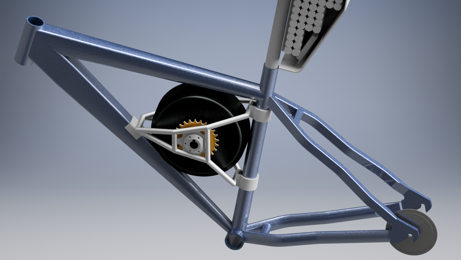 |
| Above: Final design of motor frame |
I settled on using 13mm, thick walled aluminium tube. This looked good in my opinion. Also, it was cheep and could be ordered in small quantities easily. 1/2" x 10swg available at £6 per meter on Ebay. This has an internal diameter of 6.2mm. I was able to tap and helicoil this to thread in an M6 bolt. This is how the frame separates to remove the motor.
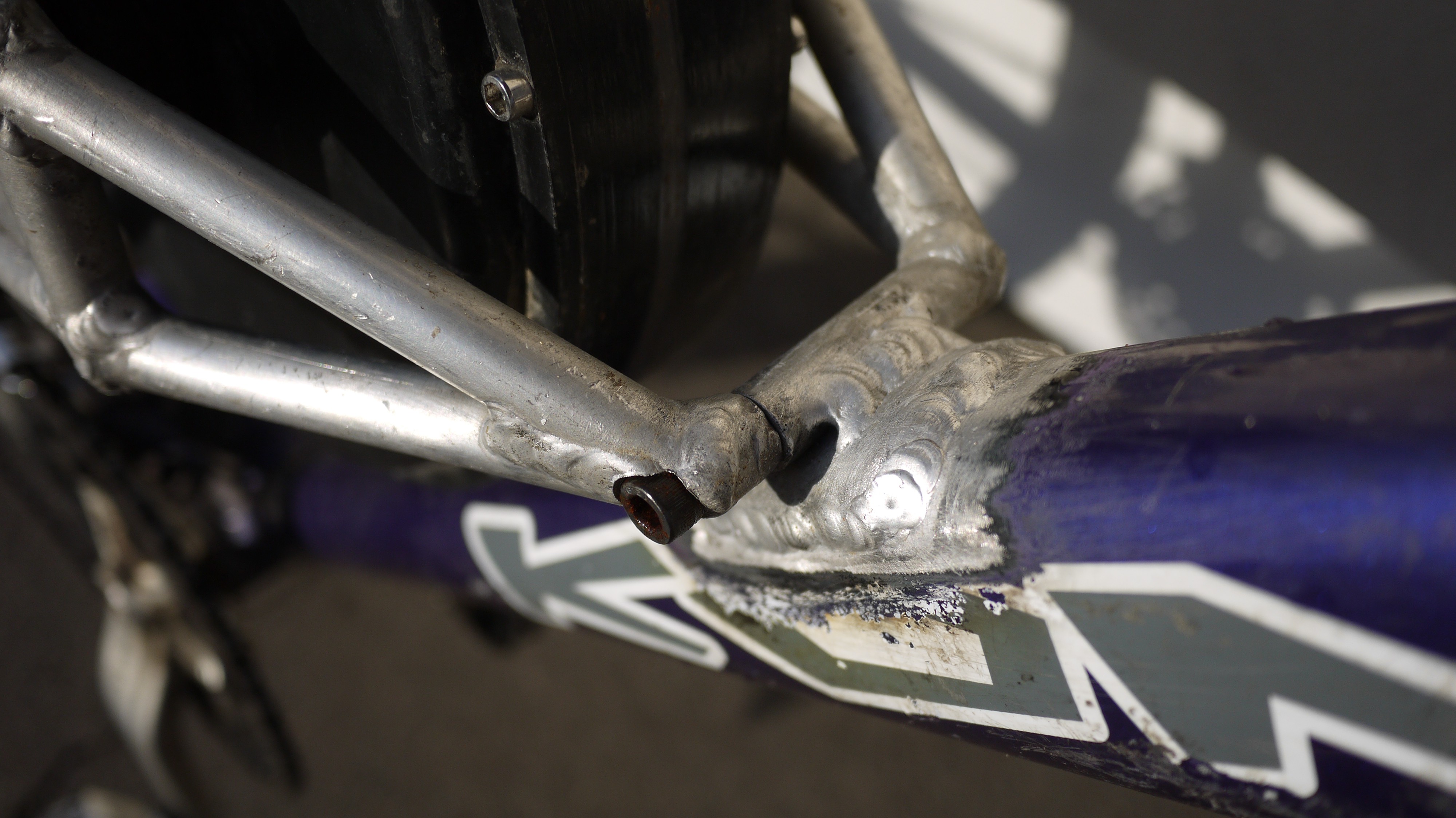 |
| Above: Frame is made of two halves secured by M6 hex hed bolts into helicoiled threaded inserts |
I had only welded aluminium a few times before and would have much preferred to use steel tubing, but this was twice the price and I would not have been able to weld it to the frame. The welding wasn’t as neat as I would have liked in places but I learnt allot doing this and the next one will be better.
Initially I wasn’t sure if the end result would justify ruining my nice bike, so the motor frame was mounted via aluminium truss clamps which comfortably fitted the seat tube. The clamps are designed for stage lighting. Once the bike was proven to work the frame was welded in permanently.
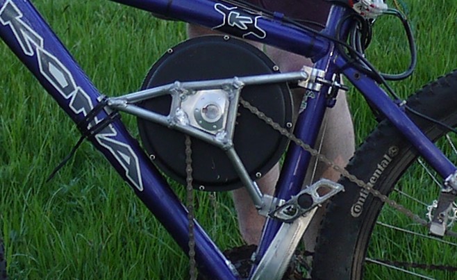 |
| Above: Truss clamps secure frame in early testing. Yes those are cable ties on the left... This did work quite well! |
Drive to rear wheel
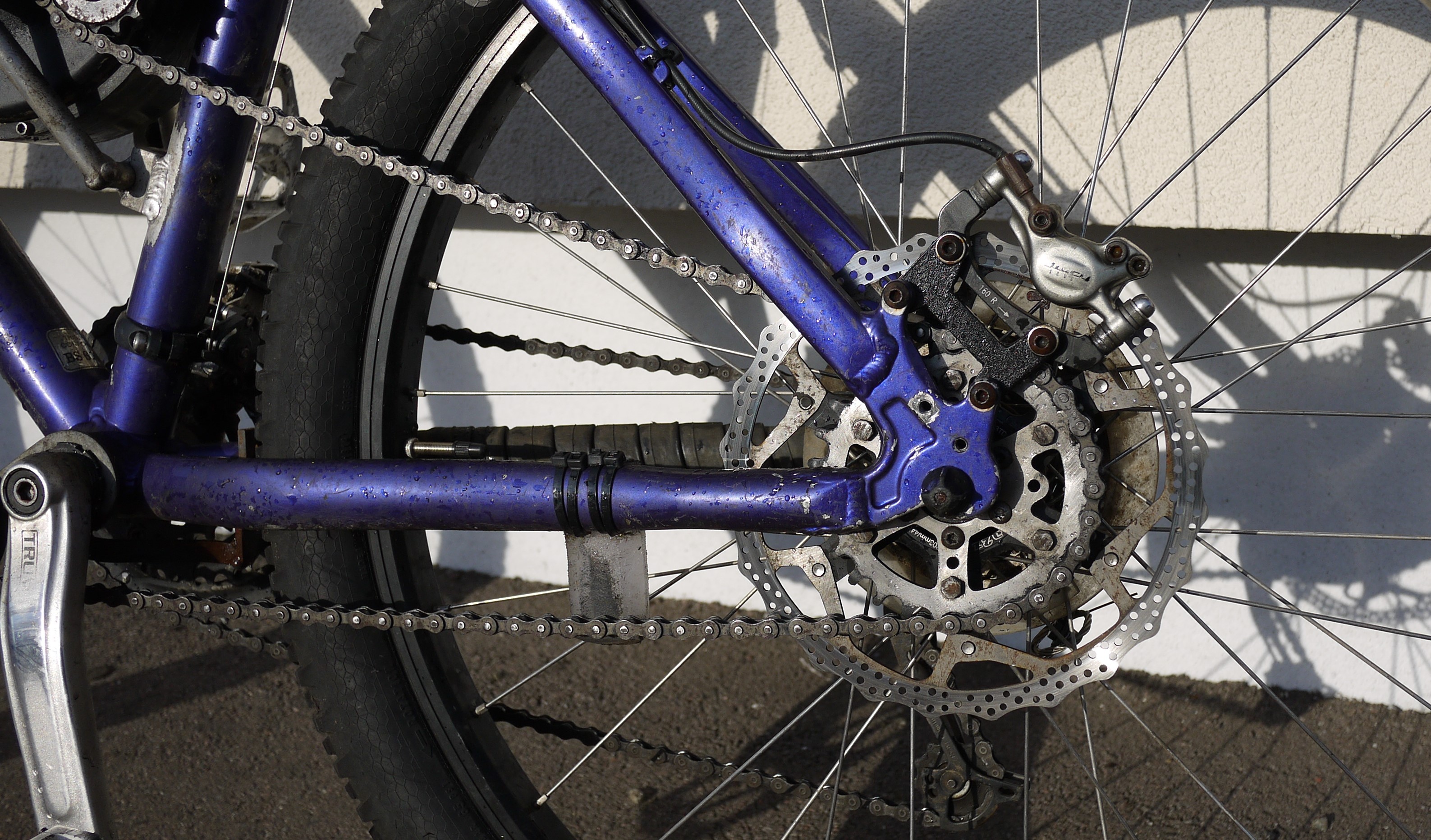
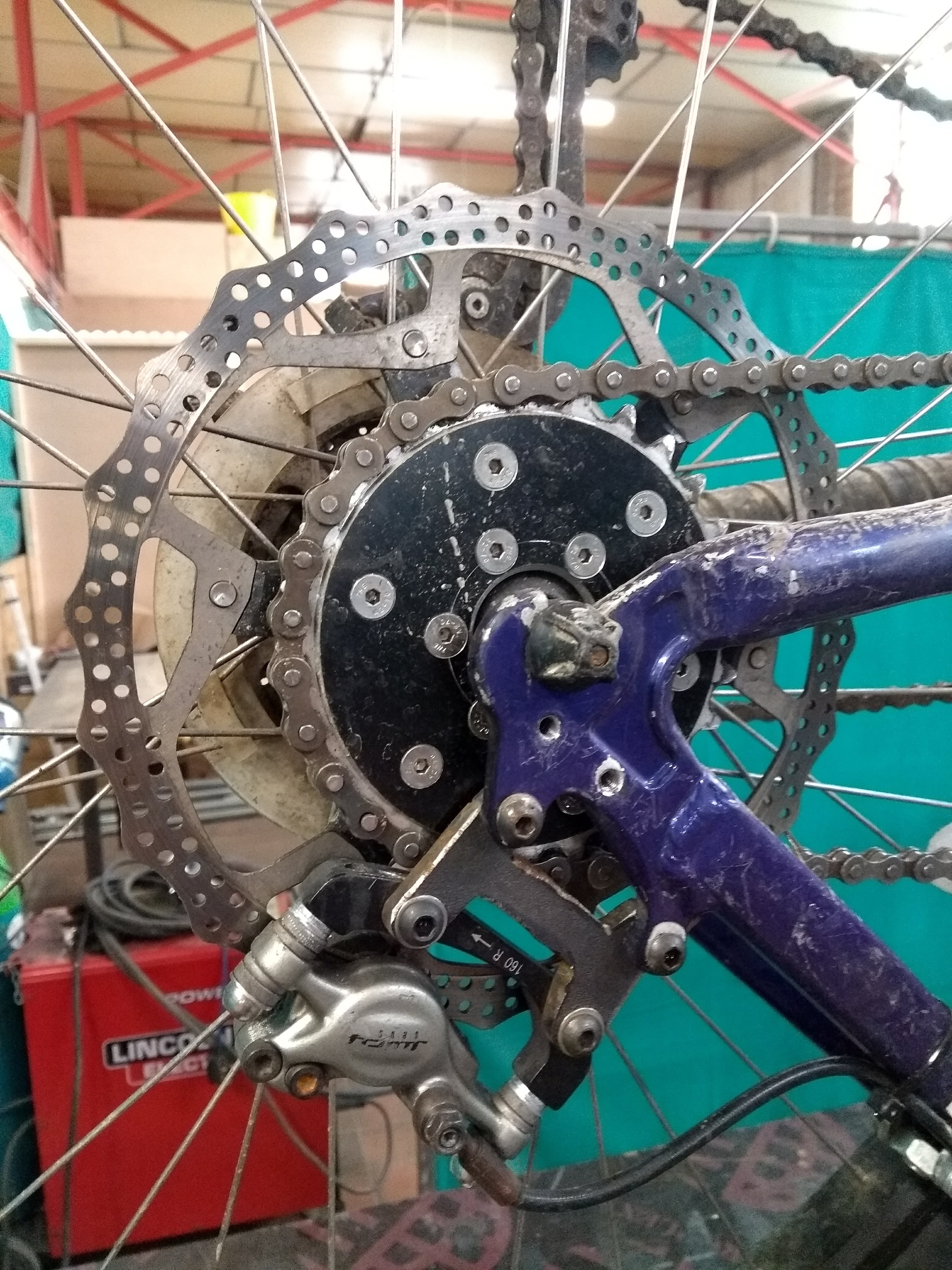
The beauty of mounting the motor into the frame is that I could get a reduction drive to the rear wheel to provide more torque. The rear drop outs on this frame (kona hoss) are very restrictive but using my cad model I determined that I could get a 28 tooth sprocket to fit onto the disk brake mount and still clear the chin stays.
 |
| Above: Sprocket mounted to disk brake hub |
Using a 203mm disk brake (with the centre machined out) I could move this inward towards the centre of the axle. The disk is mounted to the sprocket with bolts and spacers. The large size of the disk allowed the calliper to clear the chain and sprocket. A simple 6mm steel mounting bracket moved the standard IS calliper mount to the correct position.
 |
| Above: Disk is secured to sprocket |
Originally the rear sprocket was made from a modified BMX big ring. The soft aluminium wore very quickly though, and I soon ordered some custom laser cut stainless steel parts. The 3mm tooth width of standard bicycle single speed chain makes this very easy. I profiled the teeth with an angle grinder flap disk while spinning the sprocket to keep it even. Stainless, although not the best material is only a few pounds more per part and avoided me having to paint them. I have some spares of these, if you would like one please message me.
 | 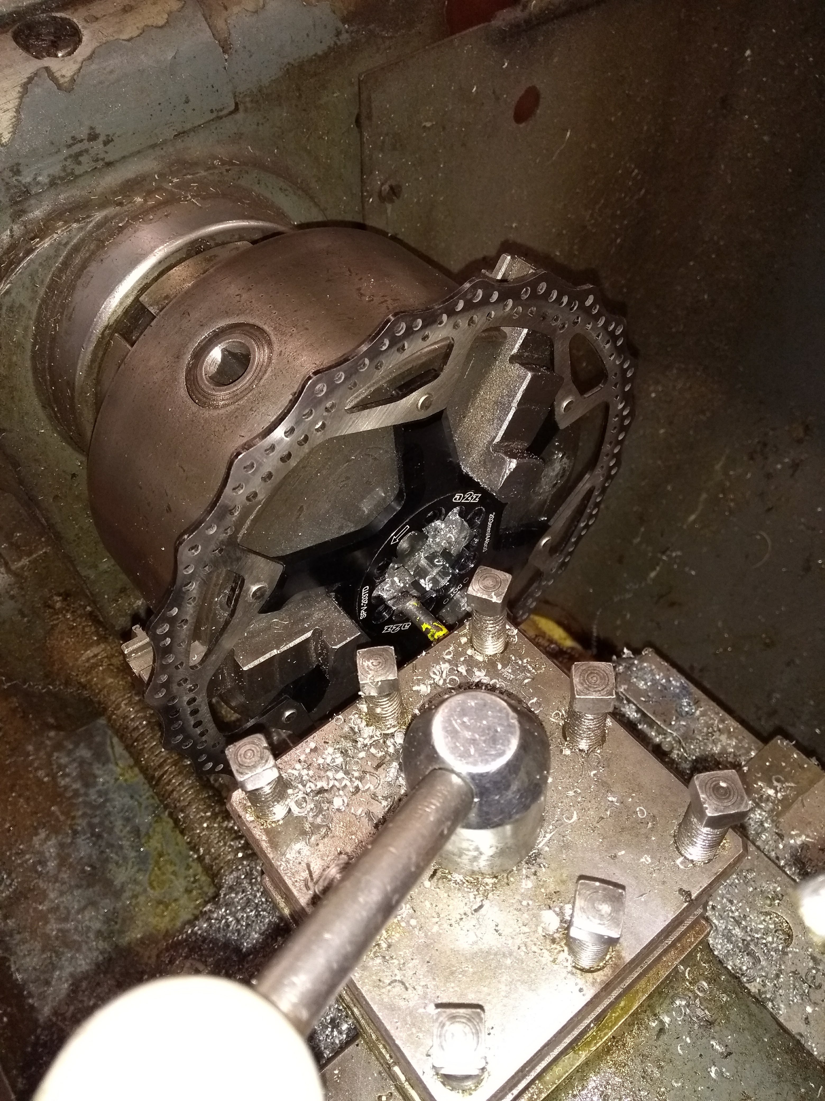 |
| Above: Original modified MBX sprocket | Above: Machining centre out of disk brake |
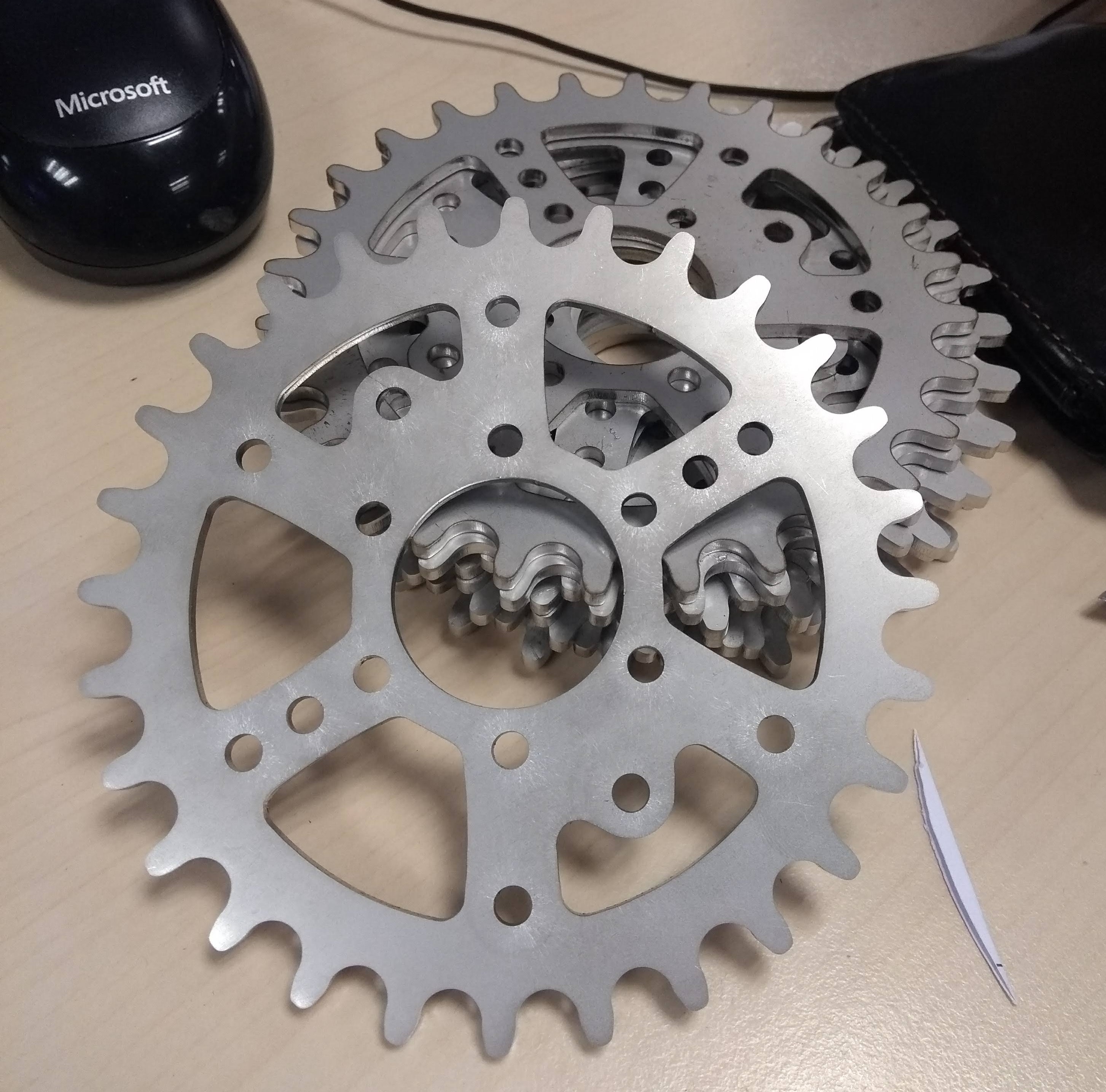 |
| Above: 3mm laser cut stainless sprockets |
The hub motor has a standard bicycle threaded freewheel mount for the drive. Threaded freewheels are available from 13 up to 24 teeth allowing me to tune the final drive ratio. I settled on a 14 tooth which is a common size and performed well (2:1 ratio). The bicycle freewheels were initially a week point in the design as the torque and high chain speeds would break them quite quickly. I was using the cheapest parts I could find though. I sprung for a Hope ‘clickster’ freewheel which has lasted hundreds of miles now with no issues.
The freewheel allows you to pedal the bike without turning the motor which was an essential requirement. I didn’t want to have to overcome the drag of the motor if I ran out of battery half way to work.
Because the position of the motor was set in place by the interference to the frame tubes it was not possible to get a direct ‘line of sight’ on either side of the chain line. Idlers had to be installed. It took a few attempts to come up with this final solution. Early on I had experimented with derailleur idler sprockets. These are always designed to work in pairs and as such do not have to have fully formed teeth to hold the chain. When used individually it is very easy for the chain to come off the sprocket.
 |  |
| Above: First idler attempts |
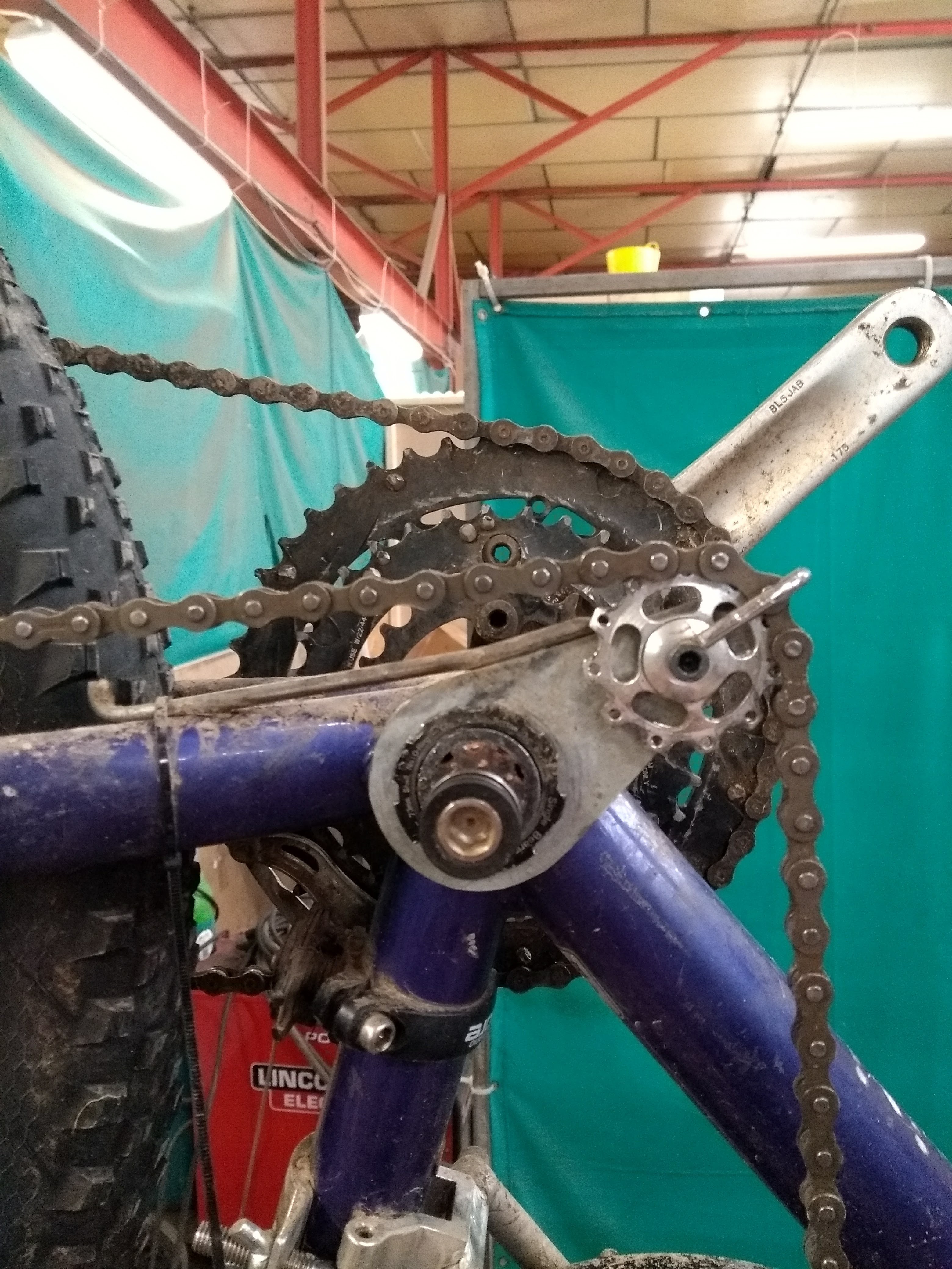
The idler on the tight side of the chain had to have a decent ball bearing to handle the load. A coincidence is that ½” British standard chain has the same pitch and roller diameter as bicycle chain. The only difference is that the sprocket width is 8.5mm rather than the required 3mm. a 16 tooth idler sprocket was modified with an angle grinder (spinning the sprocket at the same time keeps this surprisingly accurate) and works well. The chain has never come off since I fitted this.
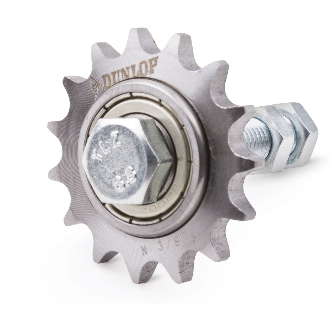 | 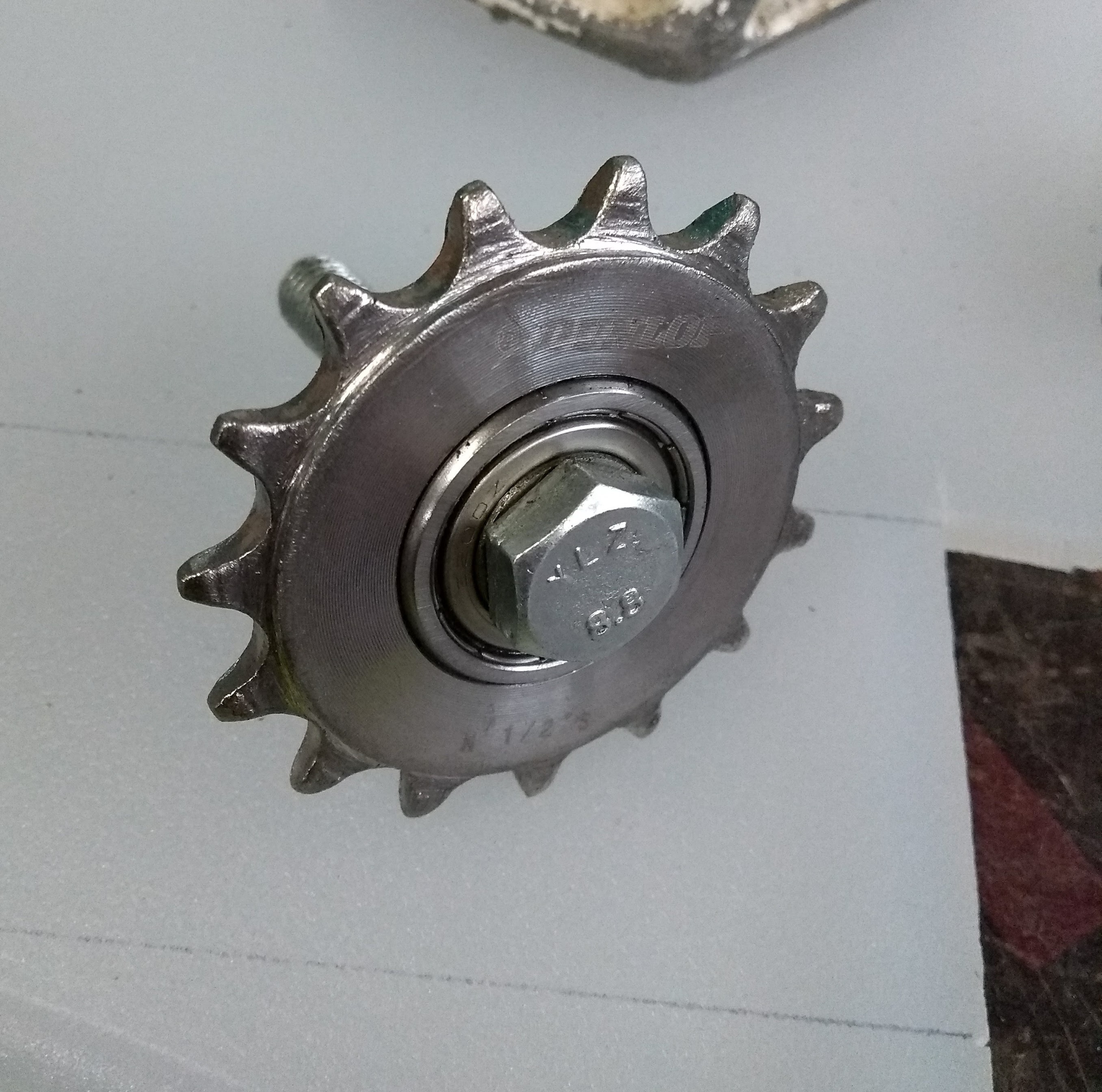 |
| Above: Idler Before | Above: Idler After |
The idler on the loose side of the chain is made using a Shimano CT-S510 chain tensioner. The sprocket and bearing part can be brought separately to the rest of the mechanism so long-term servicing is easy. After a few hundred miles this is still performing well. The idler is mounted on a custom-made arm which pivots on the bottom bracket. Rotating the bracket sets the chain tension. The angle is fixed via a slotted part which secures to the mudguard mount in front of the rear wheel.
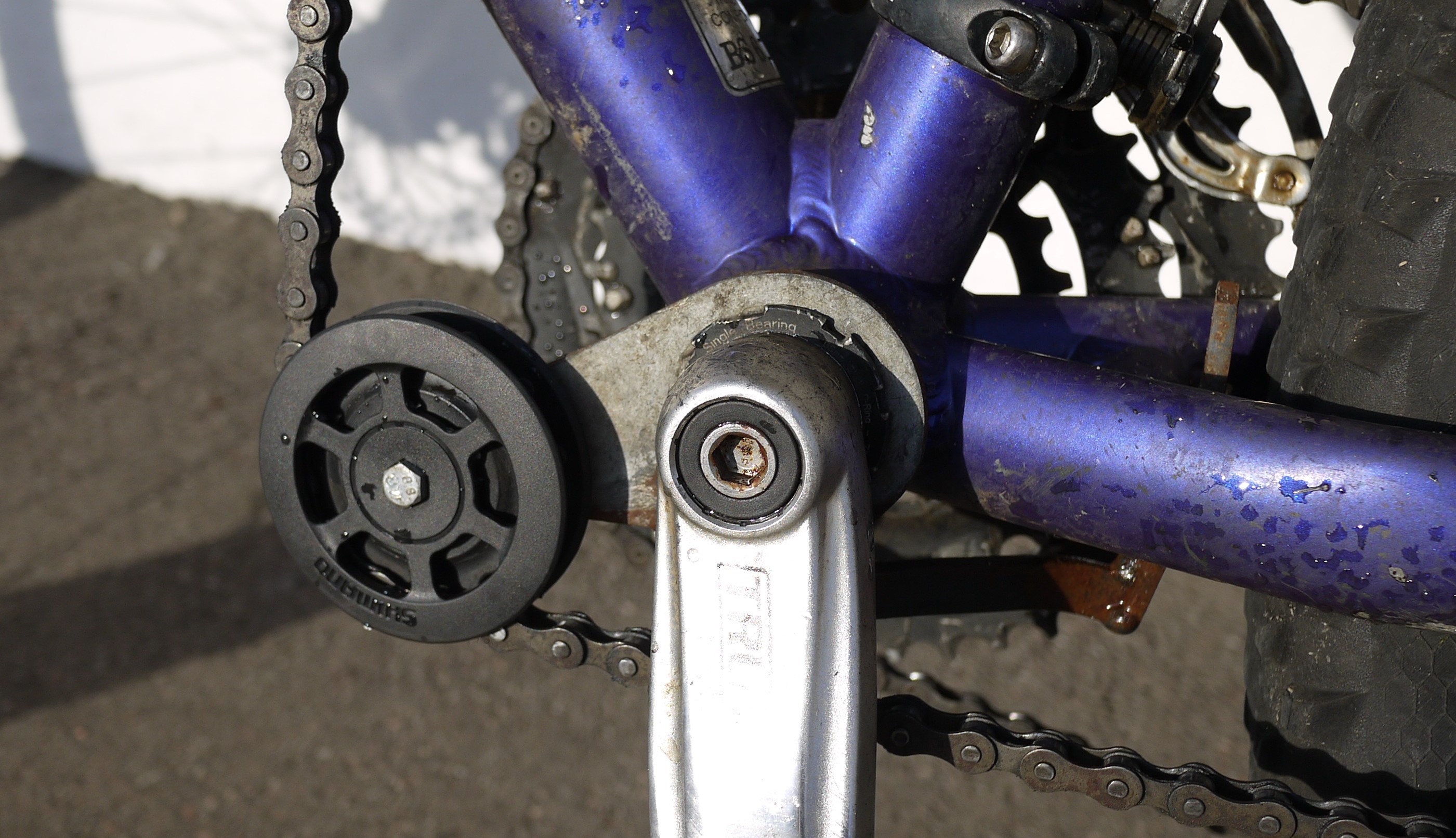 |
| Above: Idler. Still need to paint this... |
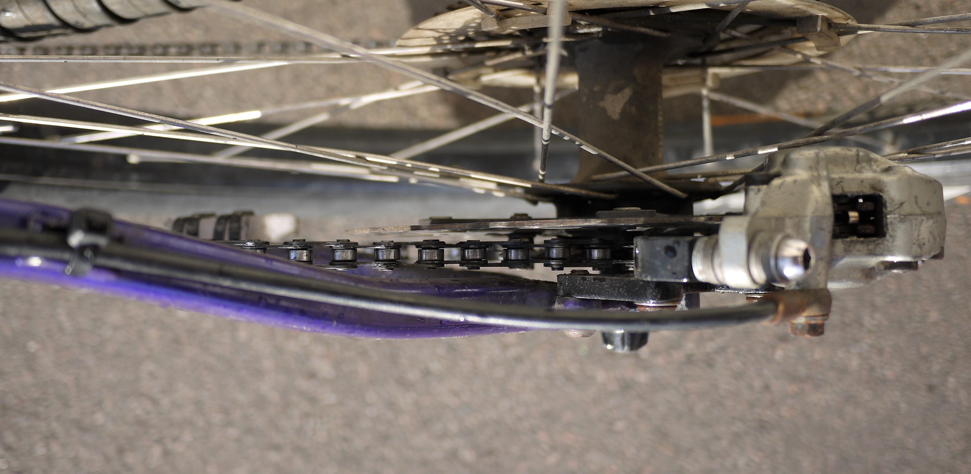
The loose side of the chain would sometimes swing into the disk brake rotor which was noisy and would potentially contaminate the disk with oil. A quick fix was a piece of plastic chopping board cable tied to the frame. This has worked so well I haven’t seen the need to change it.
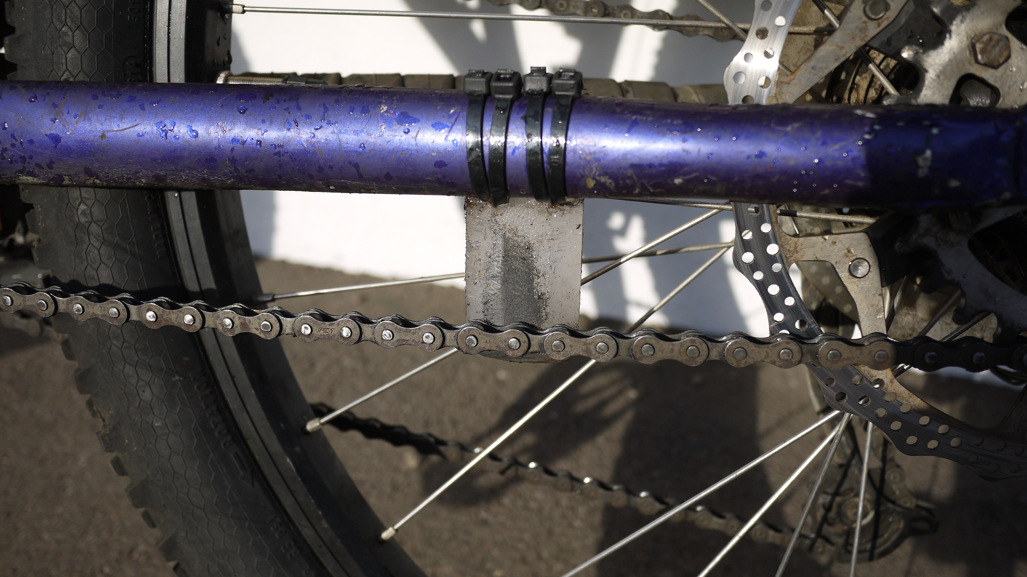 |
| Above: Chain guide on loose side of chain |
Due to width constraints between the pedals the hub motor could not be secured using the flats on the axle as a fair amount of area would have to be used to get the required strength. Instead, a 6mm keyway was ground into the thick part of the axle with a Dremel cut off wheel in a die grinder. The keyway mates with a custom machined mounting boss which fixes to the motor frame with 5 M5 bolts. On this side the threaded part has been completely cut off. On the other side one of the original M14 nuts holds the motor in position and the axle has been trimmed as much as possible.
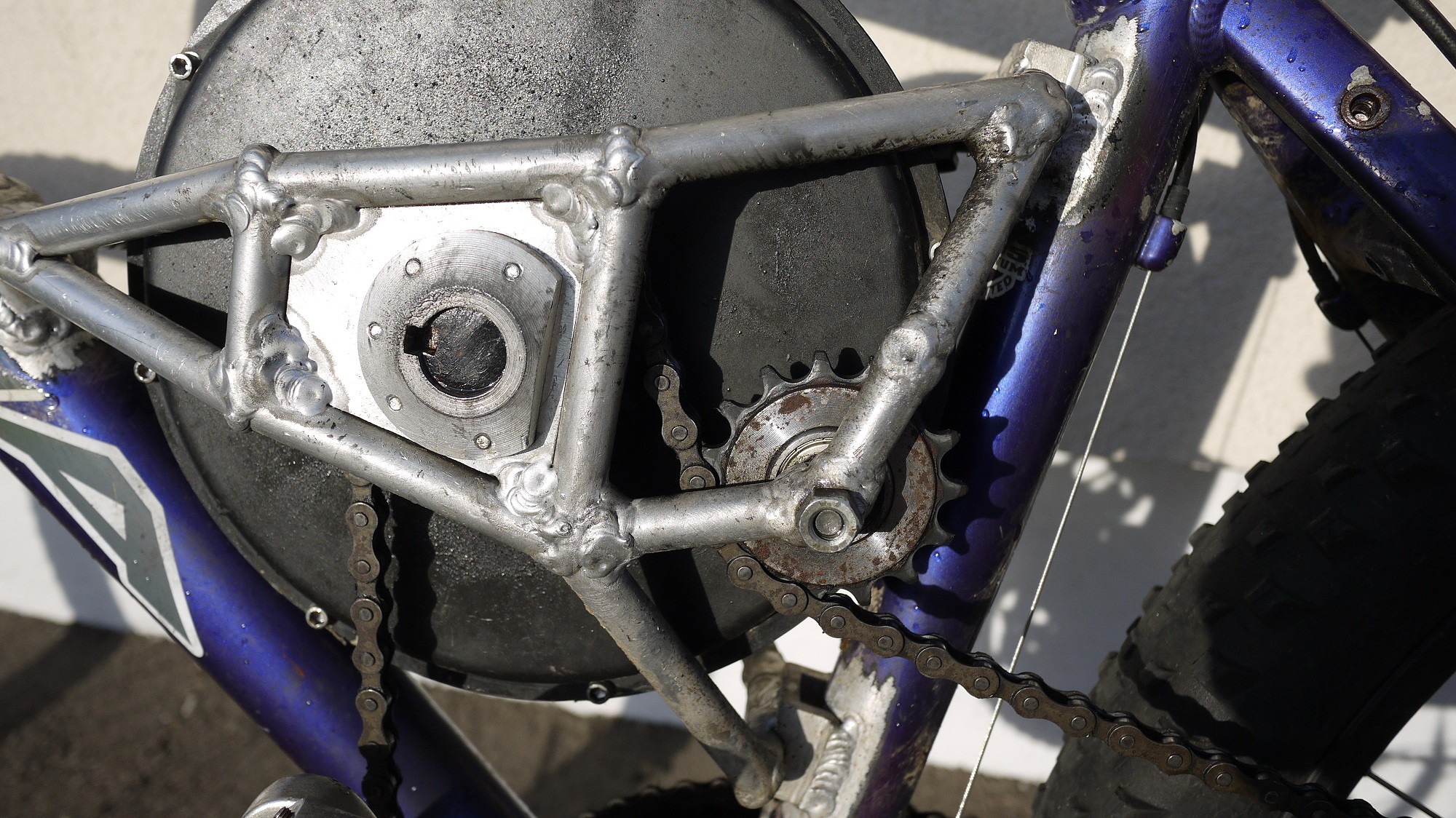 |  |
| Above: Left hand side keyway and hub | Above: Right hand side M14 nut |
Electronics & Controls
The throttle is via a half twist hall effect electric scooter throttle. I wish there were better electronic throttles available, but I was not able to find one. This does work well but it is not the most comfortable particularly off road. I had to modify one of the gear shifter leavers to miss the large part of the throttle.
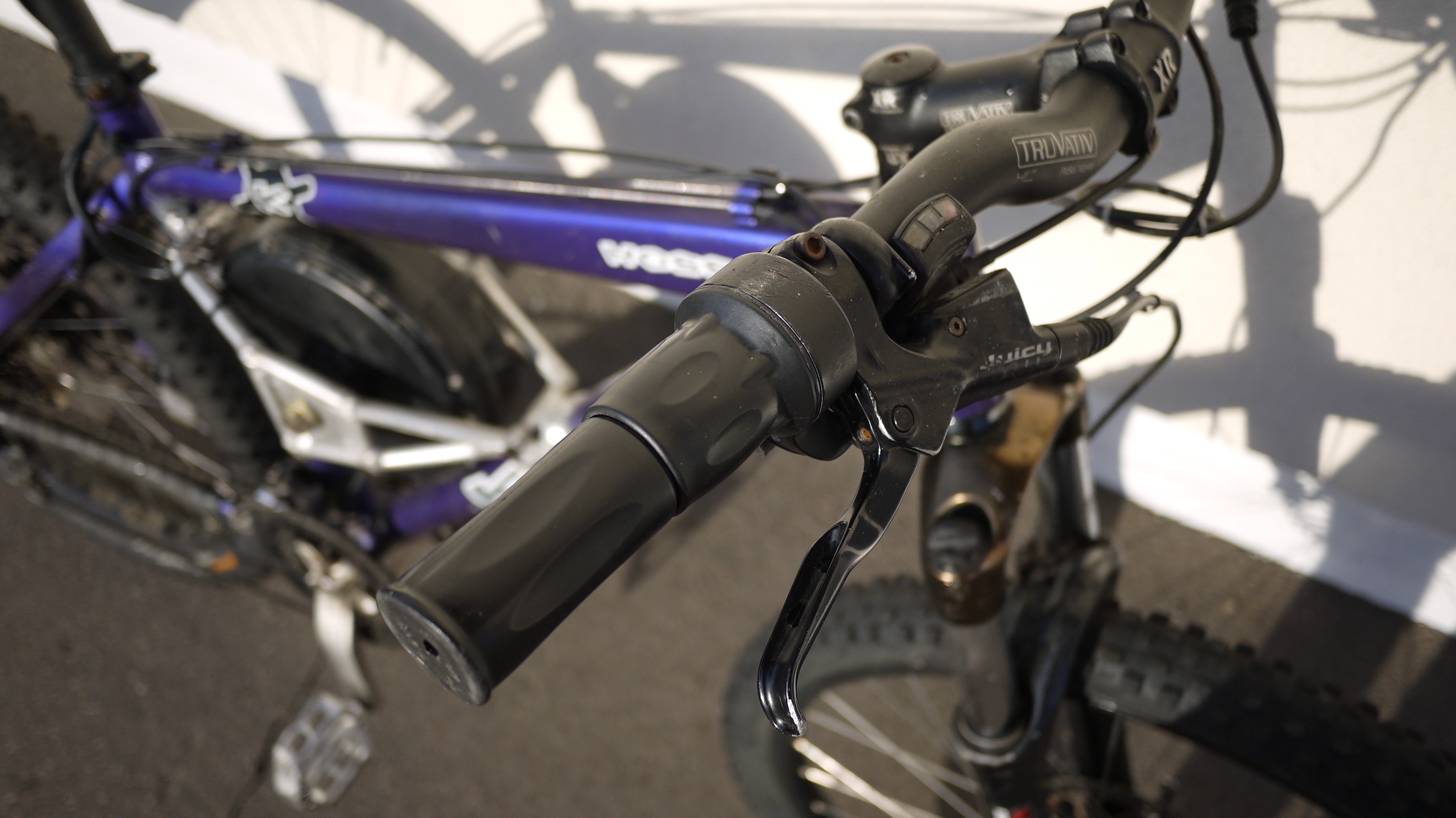 |
| Above: Horrible twist throttle |
The speed controller is mounted under the seat with cable ties. A more permeant solution needs to be found here. I will probably weld up a custom alumimium enclosure for the speed controller.
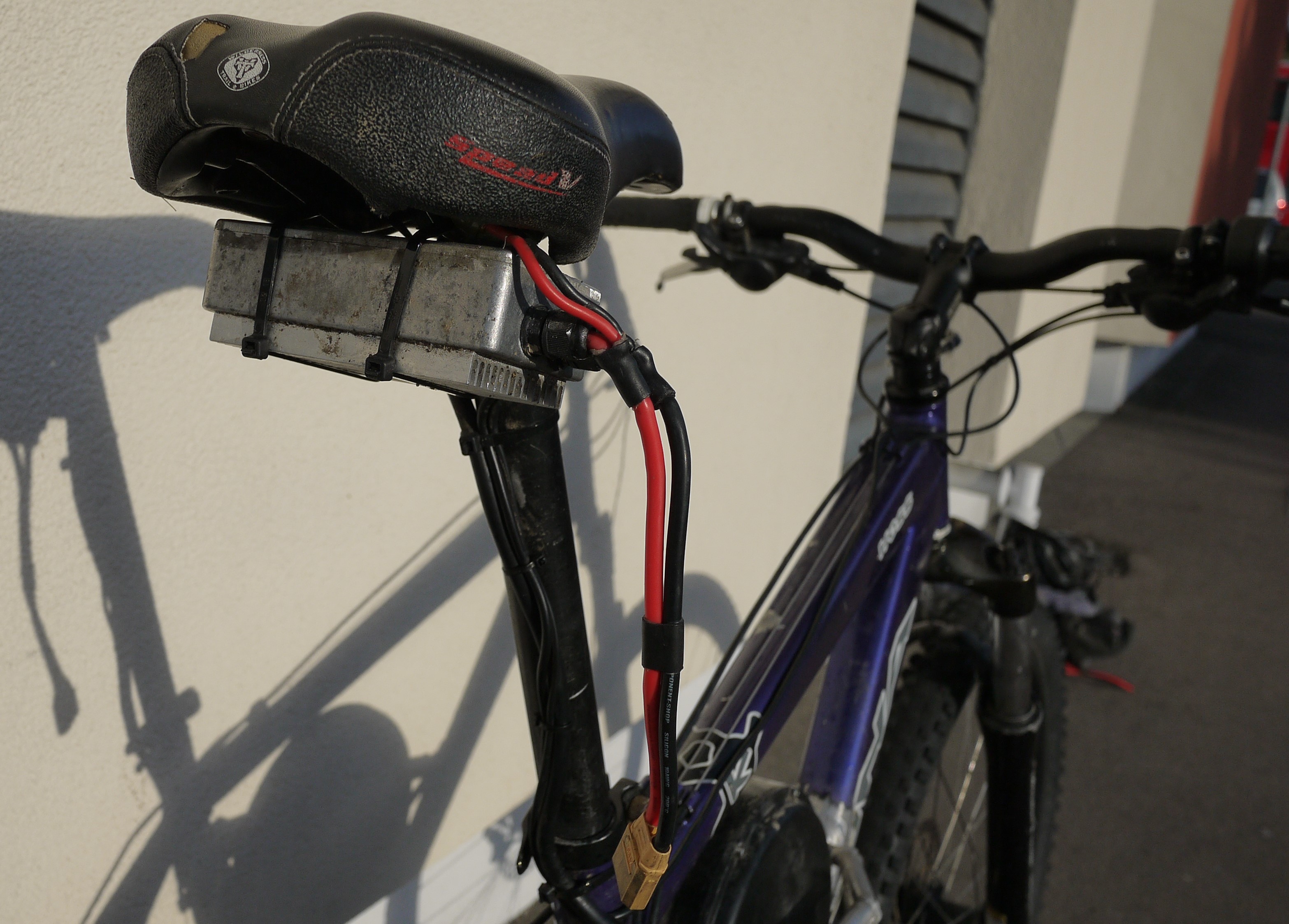 |
| Above: Speed controller under seat |
For more info on the speed controller see my other project:
https://hackaday.io/project/158982-rtvesc-a-high-current-vesc-based-bldc-controller
For commuting the battery lives inside a pannier bag with all my work gear on a rear mounted rack. For off road riding the battery is installed in a rucksack. The quick release power connector means I can safely become disconnected from the bike during crashes.
The battery is a 12 series 8 parallel pack I made myself from Samsung 25R 18650 cells (96 total).
For more information on the battery pack see:
https://hackaday.io/project/158878-900wh-e-bike-battery-pack
The throttle controls the motor via torque control to a maximum current of 70A.
Hub Motor Info & modifications
To reduce the motor size the spoke flanges and some of the outer material on the hub was machined down. I removed as much material as I could without hitting the side plate mounting bolts.
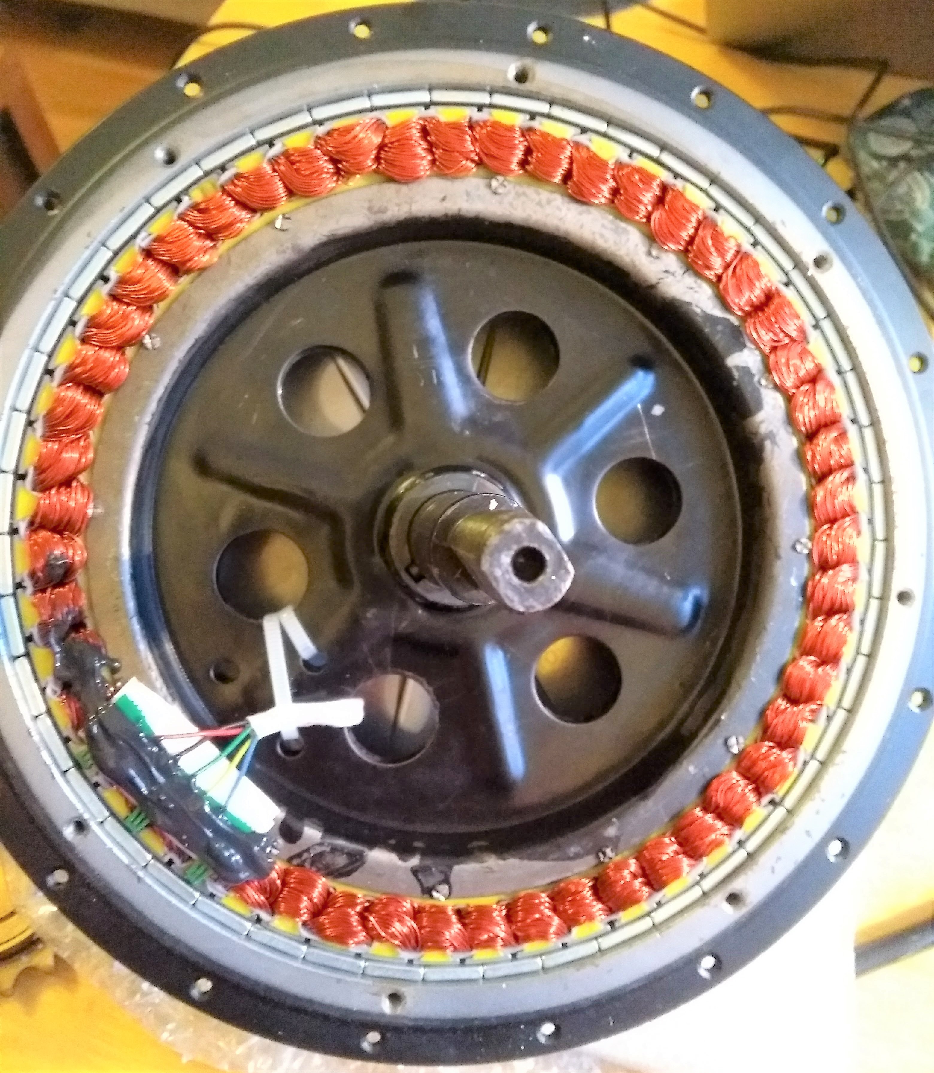 |
| Above: Unmodified hub motor |
To do this I mounted the motor in a lathe clamped onto the disk brake mount. The power cable was fed out of the back of the headstock. The axle was supported at one end by a rolling centre. The cable did whip around a bit but no damage was done
I fitted a temperature sensor inside the motor to provide a high temperature limit via the speed controller. This was not actually required and was a bit of a pain. The motor doesn’t get very hot even with a 70A current limit. This highest temperature I have seen is 60°C. The motor came fitted with a multi core cable which contains the 3 large phase wires and 5 small conductors for the hall sensors. I could not fit the extra cores for the temperature sensor through the axle with this cable. I had to replace everything with individual conductors which I was not able to seal very well. The motor is probably not very water proof anymore.
The motor runs at about 10Kv (rpm per volt), with my battery fully charged and a 2:1 ratio results in a top speed of 28mph. The motor windings as standard are configured in a star configuration. It is an easy modification to change this to delta which would give a theoretical top speed of 47mph. To be honest (thought I would never say this) the bike is fast enough as it is.
Performance in use
The performance of this bike is much better than I had expected and has changed my opinion of how good electric vehicles can be.
I can get 30 miles range on the road without the need to pedal traveling at 25mph. The chain drive and knobbly tyres are not silent but at this speed the only sound is wind noise.
The bike will happily climb very steep hills without causing the motor to heat up significantly.
I have ridden the bike nearly every day in the past few months totalling about 400 miles and it is an effortless way to get to work.
At a mountain bike trail centre with jumps and banked turns this bike ridiculous. I feel like I’m barely hanging on to the thing while flying past trees inches away! Amazing fun! I can do two laps of my local trail centre before the battery runs out which equates to about 16 miles.
There is enough torque to climb hills that would be impossible to ride up normally.
I was expecting to receive allot of hate from other users of the trails but so far everybody I have met has been very positive particularly after they have had a go. I have been making a point to ride responsibly though.
The next version needs to have full suspension as it’s hard on the knees!