 Yann Guidon / YGDES
It took almost 3 years !
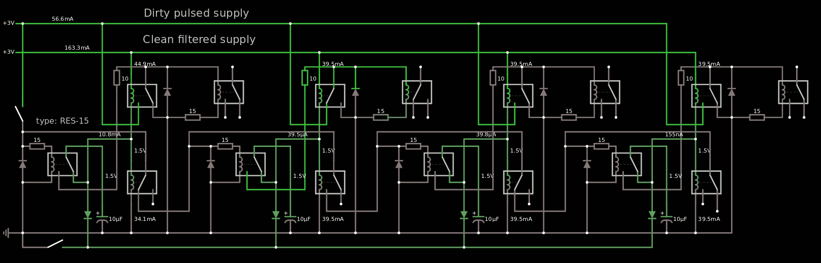
After I researched Log 10. Another relay-based divider... or is it ?, a lot of questions remained and the new version of Falstad's circuitjs with better relay models helped prototype virtually. Here is the result for a 4-stage divider:
The link is here if you want to play.
You will notice that this is NOT a ripple counter ! All outputs update simultaneously because on the falling edge of the clock input, all the latches are updated, which then routes the clock signals to the appropriate latches to update for the next cycle.
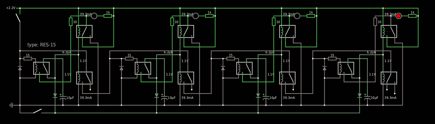
Of course the power demand is too high but there is a solution: connect the coils in series and not in parallel. The circuit will then use 2 power rails: 12V for the series circuit and the "stable/smooth" voltage for the latches (here 2.2V because I fumbled the coils' resistances but that must be tuned in the final circuit).
I have simulated the value of the capacitor down to 10µF though in practice, more headroom will be needed. The anti-rush resistor might also be increased because a low value adds noise to the "smooth rail".
The reset circuit is the usual diode in the center position, pulled to ground with a push button...
The final circuit will use 2 RES-15 per bit, the 3rd one being the input relay of the #Numitron Hexadecimal display module. That's 8 relays per counter board, 40 relays total for the 5 boards.
......
Update 20210708:
I was wrong. The display module's coils can't be part of the counting circuit because the associated contacts are used inside the module. The current design does need both SPDT of the hysteretic pair, low-side and high-side. So the display coils must be tied to the high side output, probably. The new version is here: https://tinyurl.com/yjlt5gbn
That means 3 more relays per bit, and 60 relays for the 20 bits of the whole counter. I must now manage the cascading.
.
Update 20210710:
I added the following serial chain with balancing resistors:
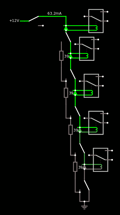
The resulting counter works nicely!
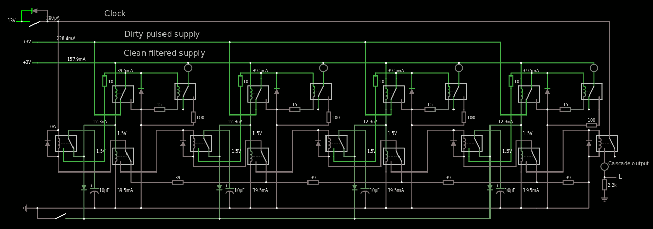
The resulting circuitjs code is getting pretty long but you gotta do what you gotta do... I hope it works for you: https://tinyurl.com/yer8l4g2
The cascade output restores the clock signal level to drive another identical circuit. There is a little one-relay delay which should not be too handicaping for small chains, but it influences the clock period for sure.
Discussions
Become a Hackaday.io Member
Create an account to leave a comment. Already have an account? Log In.