 Maximiliano Rojas
In this stage, we'll see the mechanical, mathematics and coding aspects of a delta robot that is used as a haptic device for a finger. The main goal is that the mobile platform of this robot move a tiny half sphere to simulate the touch of some virtual environment or a feedback of a sensor of pressure (or something like that), as the other modules, the idea is that it be cheap, easy to replicate and implement in other projects jointly with position and orientation acquisition system.
1 Mechanical design and mathematic model
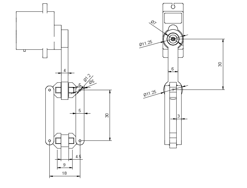
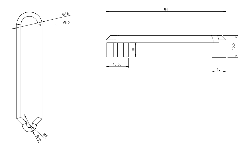
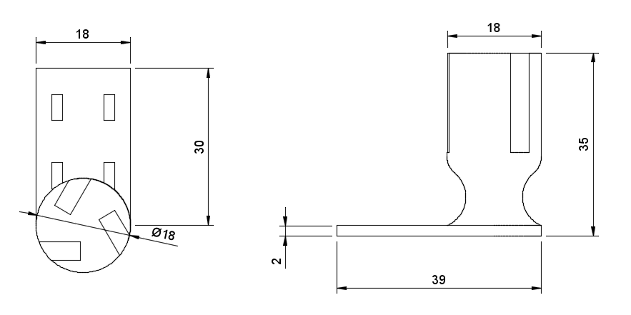
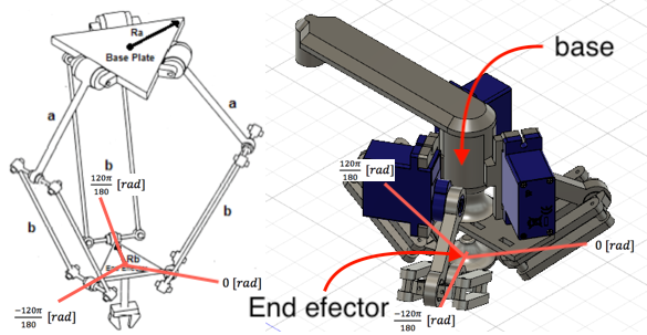
The CAD and its main measures (in mm, because metric system rules!) are:
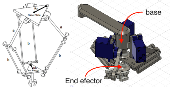

The mathematical model is based in the next image, there you can see letters (like A, O, B, P, and C) that represent points in a 3D space so, OA represents the vector that starts in point O and ends in point A, the minuscule letters represent the magnitude of this vectors (how long is). With this, we can start to make spacial relations between those vectors and, for comfort, operate them as matrixes, so:
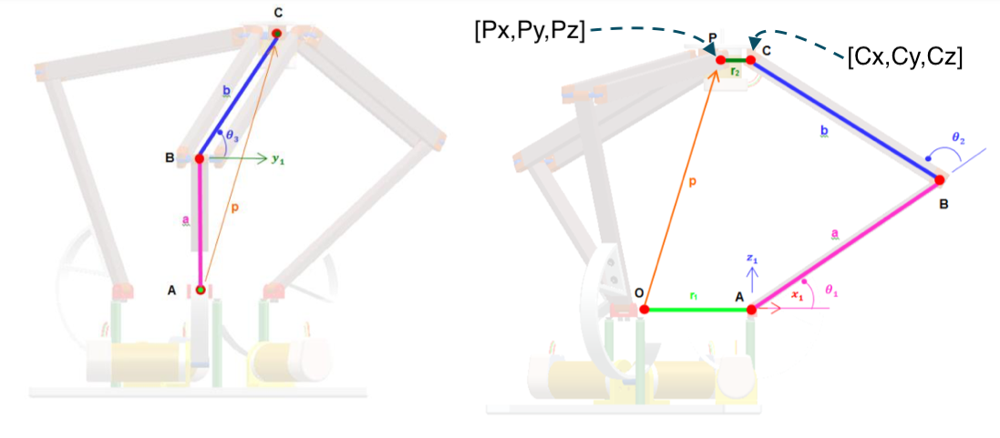
Where "O" can be consider as the origin of the frame, while "P" is the middle point of the mobile platform, to save time (currently I'm in the middle of exams D: prey for me PREY FOR ME) only one arm will be analyzed and, through the rotation matrix in z (Rz), the other arms will be extracted immediately, so:
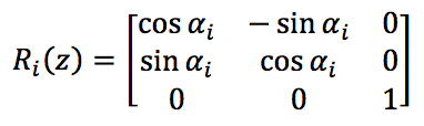
Where:

And corresponding to the angle of the arms, and for extension, their position, as the image bellow shows:
The other vectors are:

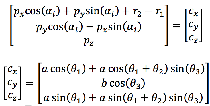
Is important to keep the goal in mind, we must find the theta angles that correspond to the angles of the arms, so, we can think in make a system of equations from the vectors that represent the structure of one arm:
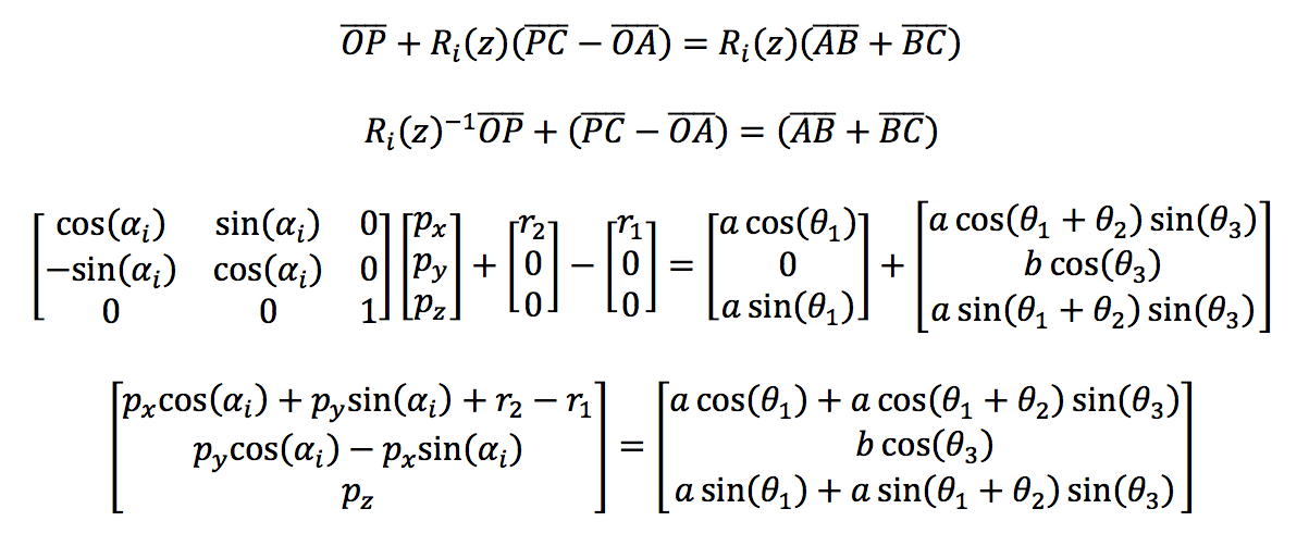
If we look carefully both sides of the equation can represent the vector of the point [Cx Cy Cz], but only in the left side all variables are known, then, for simplicity, it can be represented as:
Now theta 3 of the ith arm can be obtained directly from the matrix as:

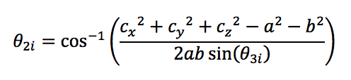
Sadly the ith angle theta1 and theta2 can't be obtained directly from the matrix, so, taking advantage of the trigonometric transformations, the square of the elements of both sides of the equation will be added, so, for theta2 of the ith arm:

From the last expression, theta2 can be easily obtained:
To obtain theta1 of the ith arm, the column elements of both sides of the matrix equation will be added, so:
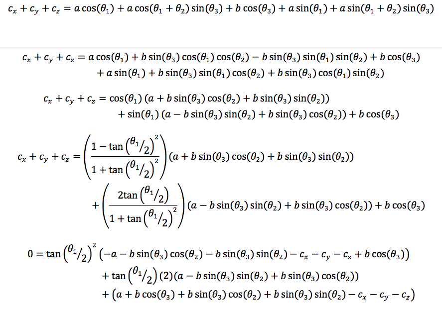
To improve the visual aspects of the last equation the next auxiliary variables will be used:
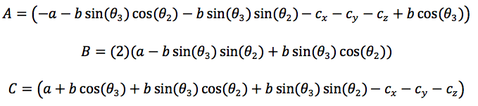
Finally, the second order trigonometric equation is obtained:
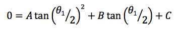
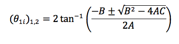
So, the solutions for theta1 of the its arm are:
The video bellow shows the Matlab validation and real test of the equations obtained:
2 coding
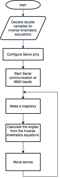
I've not too much to say about coding, you know, just write the equations and give it a coordinate to calculate the right angles, this is the magic of model something mathematically if your assembly is correct, the real device must respond, in this case, as the simulations show, nevertheless here you have the flowchart of the program:
3 application
The application for this module will has a special section due the extension of it.
Discussions
Become a Hackaday.io Member
Create an account to leave a comment. Already have an account? Log In.