 greg
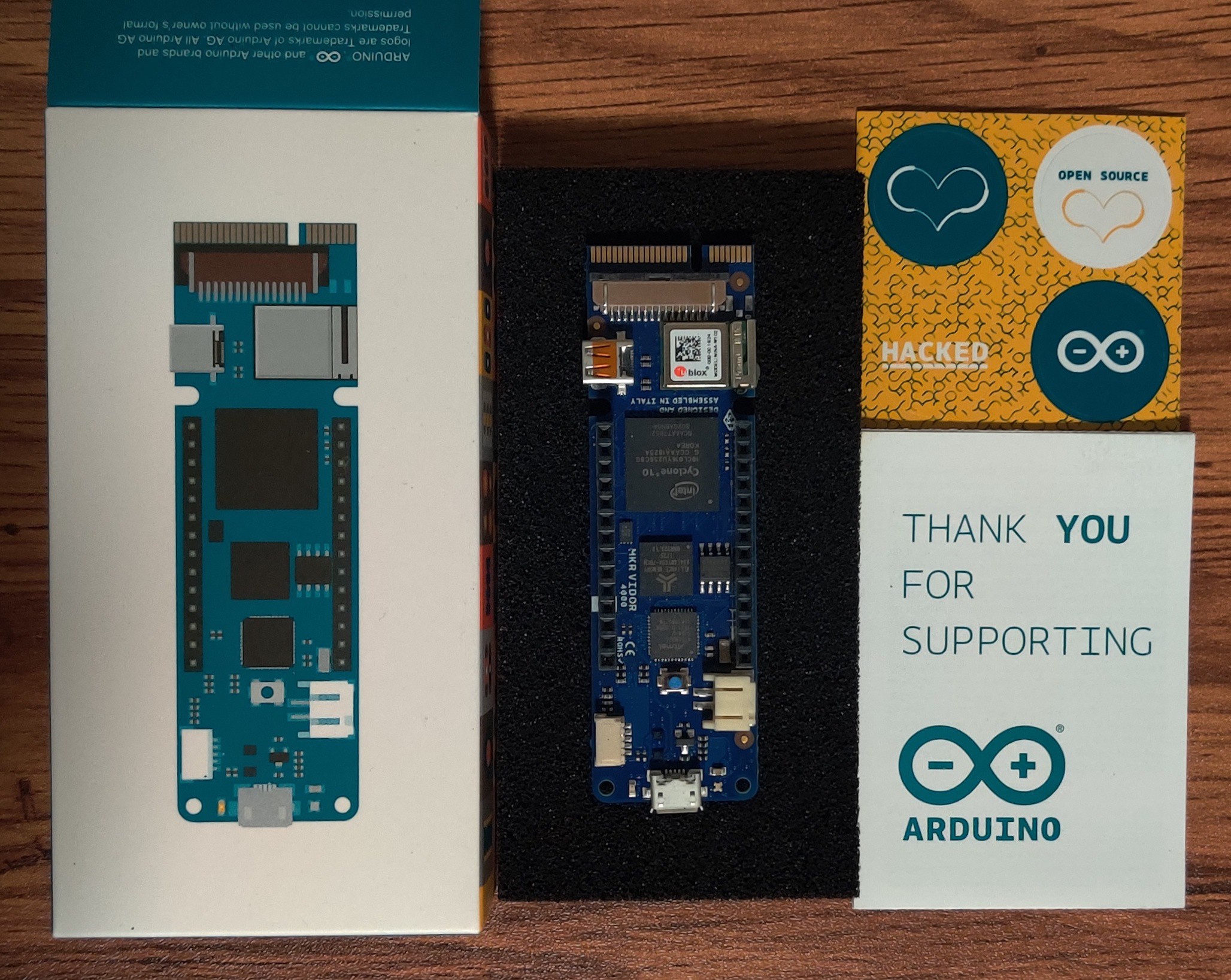
gregReceived the Arduino MKR Vidor 4000 this week.
First order of business is upgrading the bootloader. It is the same SAMD21 with the same LED pin as the MKR Zero so rebuilding the https://github.com/adafruit/uf2-samdx1 was very straightforward. All I really needed to do was change the drive label. Long term I probably need to get a new VID/PID for this board with the UF2 bootloader. I didn't want to wire up my CMSIS-DAP debugger, so I used the .ino file generated by uf2-samdx1 along with the Arduino IDE to update the bootloader.
Next, I wanted to start porting CircuitPython to allow me to access the FPGA with the JTAG library. I ran into some issues building mpy-cross that I still need to work through.
I'm continuing to look at strategies for loading images into the FPGA. If I were designing the board, I would probably connect the MCU up to the config flash in parallel, but I did not design this board so I am stuck with their connections. Reviewing the schematic in more detail I see that they only connected the JTAG signals. There are many of the I/O connected in parallel with the MCU I/O and to the header pins, so I could also use those as side channel to load images through a friendlier interface than JTAG. I am wondering how large an image would be that only wires up MCU I/O to the SPI signals for the configuration flash. If it is small enough, I can include it in the MCU code, so it can be loaded into the FPGA, then load the flash directly with a SPI interface. It would be easier to implement UF2 loading through a SPI interface than it would be through JTAG.
This begs the question. Where does the FPGA loading code belong? Should it be part of the MCU bootloader so that you can update both the MCU and FPGA images from the same bootloader? Or, does it belong in the MCU application? The bootloader should be small, so I need to consider the code size. It might be possible to fit an SVF processor in the bootloader, but I doubt there would be room for even the smallest FPGA image to use the SPI flash trick.
It is also worth considering what the MCU application will be doing along with the FPGA. The SAMD21 is not a power house. It will probably function mostly as a USB interface to the FPGA. It is reasonable to consider that the MCU application could contain both the FPGA update code and the FPGA interface code. CircuitPython might not be the ideal choice with the limited memory available on the SAMD21. It may force splitting the loading and interfacing code into separate images.
Discussions
Become a Hackaday.io Member
Create an account to leave a comment. Already have an account? Log In.