 Sven Dahlstrand
Using the six-pin connector, a Game Link Cable and two Game Boys you can play against – or team up with – a friend. In this project, though, I'm making an LED obey my every command instead.
 ___________
|  2  4  6  |
 \_1__3__5_/
EXT connector on my Game Boy Color.
My Game Boy Color names the six-pin connector EXT. It's located at the top left side and looks roughly like the above figure. I've numbered the pins from 1–6.
Luckily for me someone has figured out the pinout already. I cut my Game Link Cable in half to figure which colored wire connected to which pin number, using the continuity test functionality of my multimeter:
| Pin # | Name | Description | Wire color |
|---|---|---|---|
| 1 | VCC | +5V | Orange |
| 2 | SOUT | Serial out | Brown |
| 3 | SIN | Serial in | Green |
| 4 | SD | Not used | Yellow |
| 5 | SCK | Serial clock | Blue |
| 6 | GND | Ground | Red |
It looks promising! I've got +5V and ground for the LED and should be able to control it using the serial out and clock somehow.
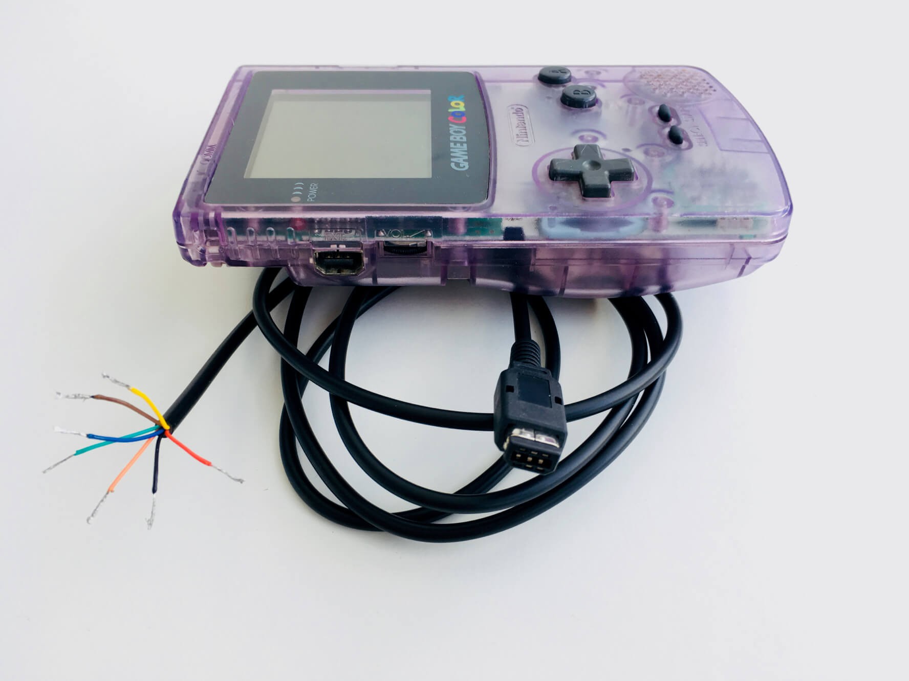
A closer look at the cable and connector.
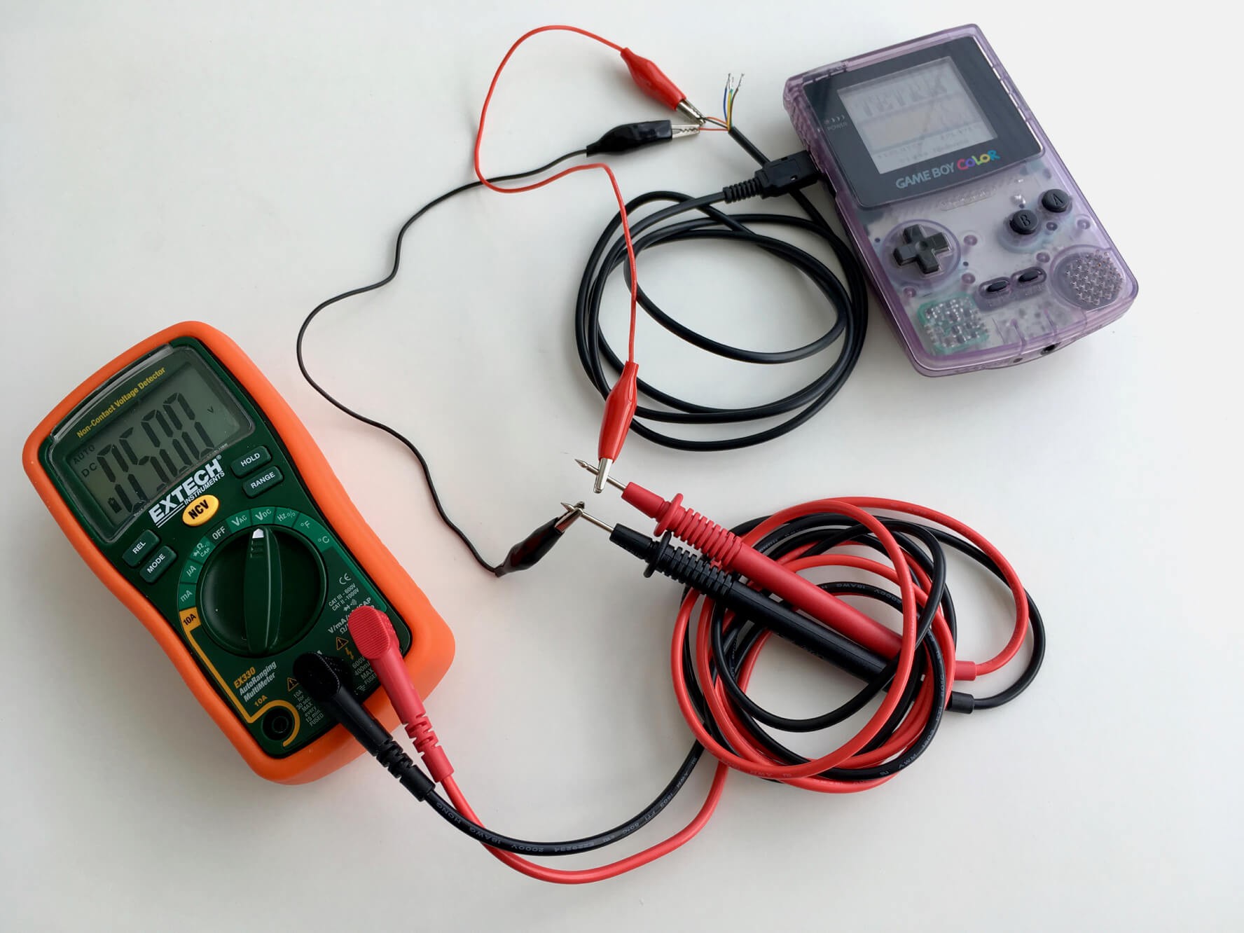
The multimeter hooked up to the cable and measuring +5V.
Discussions
Become a Hackaday.io Member
Create an account to leave a comment. Already have an account? Log In.