A simple test set-up was built to check the ALU. Here it is:
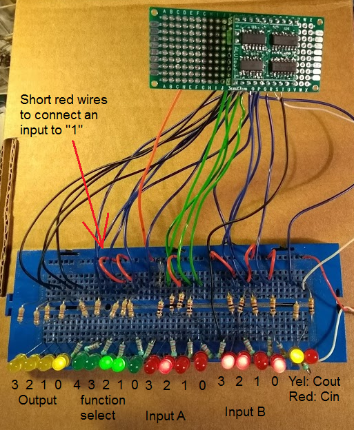
In the picture, the function "ADD" was selected (green LEDs), and the inputs were 0100 and 1101 (on the red LEDs). The output is 0001 (yellow LEDs), and a carry is generated (the yellow LED at the right side). Several functions and input combinations were checked and all were ok.
The outputs have LED's, and the inputs have a "switch" (and a LED to check operation of the switch), like this:
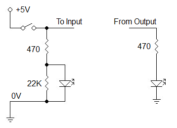
The switches are just small red wires on the breadboard that connect an input to "1". Note that the input LEDs have a 22K resistor to define a good "0" level when the switch is open. The red LEDs were very bright, their series resistors were changed to 1K. (This last schematic was drawn with the Klunky schematic editor, an easy-to-use editor for simple circuits, that runs in your browser.)
Discussions
Become a Hackaday.io Member
Create an account to leave a comment. Already have an account? Log In.