 K.C. Lee
I got one of those Leed's USB power bank from my apartment building during a planned power outage. It blew up when I tried to charge it. There wasn't a whole lot I could reverse engineered from the dead parts. There was a 5-pin and a 6-pin chips and a bunch of passives. My understanding is that it uses an inverting buck boost converter for both charging and output as the VUSB pins of both the USB connectors are connected together.
I finally got around to rebuild it from scratch this weekend with what I have on hand. The parts I have were from aliexpress before the big chips shortages. I use a LTC4054 Li-ion charger chip and a MT3608 boost converter.
The charging rate is limited by heat dissipation on a tiny single sided PCB. The output current is limited by the Schottky diode, inductor and battery discharge rate to about 1A (or slightly higher) or so matching to the original power bank.

Power bank schematic
Q1 and the 1M pull down (R3) is used to invert the logic level of my switch to drive the Boost converter Enable pin. The switch is also used to connect the R2 from the voltage divider feedback to the ground. RGB LED is used as for Charging/Operating indicator.

The converter goes into a PFM (Pulse Frequency Modulation) power saving mode for low current loads.
I used Green LED as they have the highest efficiency. It is connected across the inductor to further reduce idle power. It only get energized only when the boost converter is supplying current to the load. The brightness is proportional to load. Fancy!
Your USB power bank might have a detection circuit that shuts itself off. I could have used a low power microcontroller that wakes up every hundreds of milliseconds to detects voltage drop across the Schottky diode to turn on the converter.
The idle current is about 200-300uA while maintaining a 5V output when the external USB device not drawing power. That seems high, until you realize that it'll take thousands of hours before the battery is drained.

Power bank PCB
My PCB is taped to the existing stripped down PCB. I had to cut the VBUS trace between the USB connectors. The blue wires are for the RGB LED.
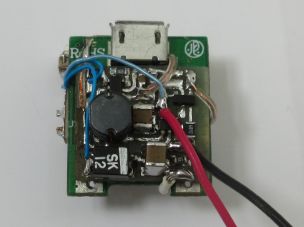 Populated PCB (I only have 1A/20V Schottky diode.)
I modified the USB A connector to include a contact switch that is grounded when the USB A is plugged in. This is used to enable the boost converter circuit.
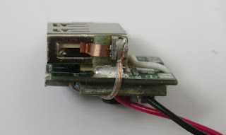
Modified connector to sense presence of USB plug

Red LED = Charging

Green LED = Operating. Brightness proportional to load
Yellow is when both are connected, but that doesn't usually happen as the connector spacing is too closed together.
https://hw-by-design.blogspot.com/2023/04/usb-power-bank.html
Discussions
Become a Hackaday.io Member
Create an account to leave a comment. Already have an account? Log In.