 T. B. Trzepacz
I got tired of the speaker flopping around and the metal bits on it threatening to short circuit stuff, so I designed a 3d printed plastic mounting ring for it. Here is the view from Cura.

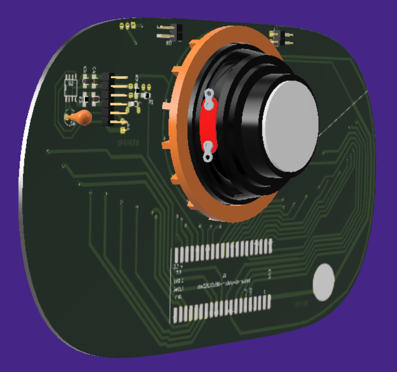
Here is a 3d rendered view of how it mounts on the back. I colored it orange so that it would stand out, but the real one is designed to be unobtrusive.
That's not a model of the real speaker, just the closest equivalent I could find.
Notice that there are gaps spacing it away from the PCB. That's because the real PCB has all sorts of solder and bodge wires on it and I needed some sort of spacer to get around all of that. The production design can use a much slimmer profile.
And the front view.

So here is the actual 3d printed output. Came out pretty much exactly as designed.

And here it is in the current prototype. Looks ok from the front, but if you look carefully you can see huge gaps in the bottom and top. That's because it DIDN'T FIT AT ALL! My "solder-glued double width board" is kinda missing a mm or two in the middle where the boards join, probably due to the width of the end mill used to cut the board. That makes the inner diameter much smaller than expected. Rather than redesign and reprint for this one-off test board, I just munged it with nippers until I was able to jam it in. Side effect; the friction fit is ~*REALLY*~ good....

Here is the back view. You can see that the actual connector for attaching the speaker didn't fit either, and I had to actually cut a hole in the ring for the cord to go through. You can't tell, but I also had to cut a bunch of supports down on the bottom because of the various bodge wires that were pushing the ring up to a point where it didn't grip on the inside of the hole. Worse, the spacers that were supposed to go between the raised spots on the PCB ended up right on top of the vias, which were what I really was supposed to be avoiding, I managed to twist it a little bit to solve this, but I should really fix that before I make another one.

Anyway, despite all of the errors, it does the job for now.
I'm trying to make the thing a little more stable before I record my final necessary song video for the Hackaday prize entry. Just a couple of days left!
Discussions
Become a Hackaday.io Member
Create an account to leave a comment. Already have an account? Log In.