 Michael Delaney
This project began with a simple goal, to build an inexpensive FPV monitor that could reliably be used to view 5.8GHz video transmissions from my FPV quadcopter, but it very quickly became much more than just quick build.
The construction of the circuit was overall quite simple, just a few connections between the Arduino, RX5808, and LCD was all that was needed to build a functional prototype on a breadboard.

After this early success, I decided to design a PCB for the circuit as I noticed the design was somewhat bulky on a protoboard and the castellated edges on the RX5808 would make soldering the module directly to a PCB relatively easy. Rather than unnecessarily design a two layer PCB and wait a few weeks to receive the design from China, I decided to make a single sided PCB layout and attempt to etch the design myself. While I could have used my X-Carve CNC to mill the PCB layout, I ultimately decided to experiment with laser ablation using my new Glowforge laser cutter.
For my first attempt I tried coating a blank PCB with sharpie and then etching the coating off with the laser, but due to the inconsistency of the coating the resulting board ultimately had streaks of marker left on the copper which caused a number of issues when etching the design.
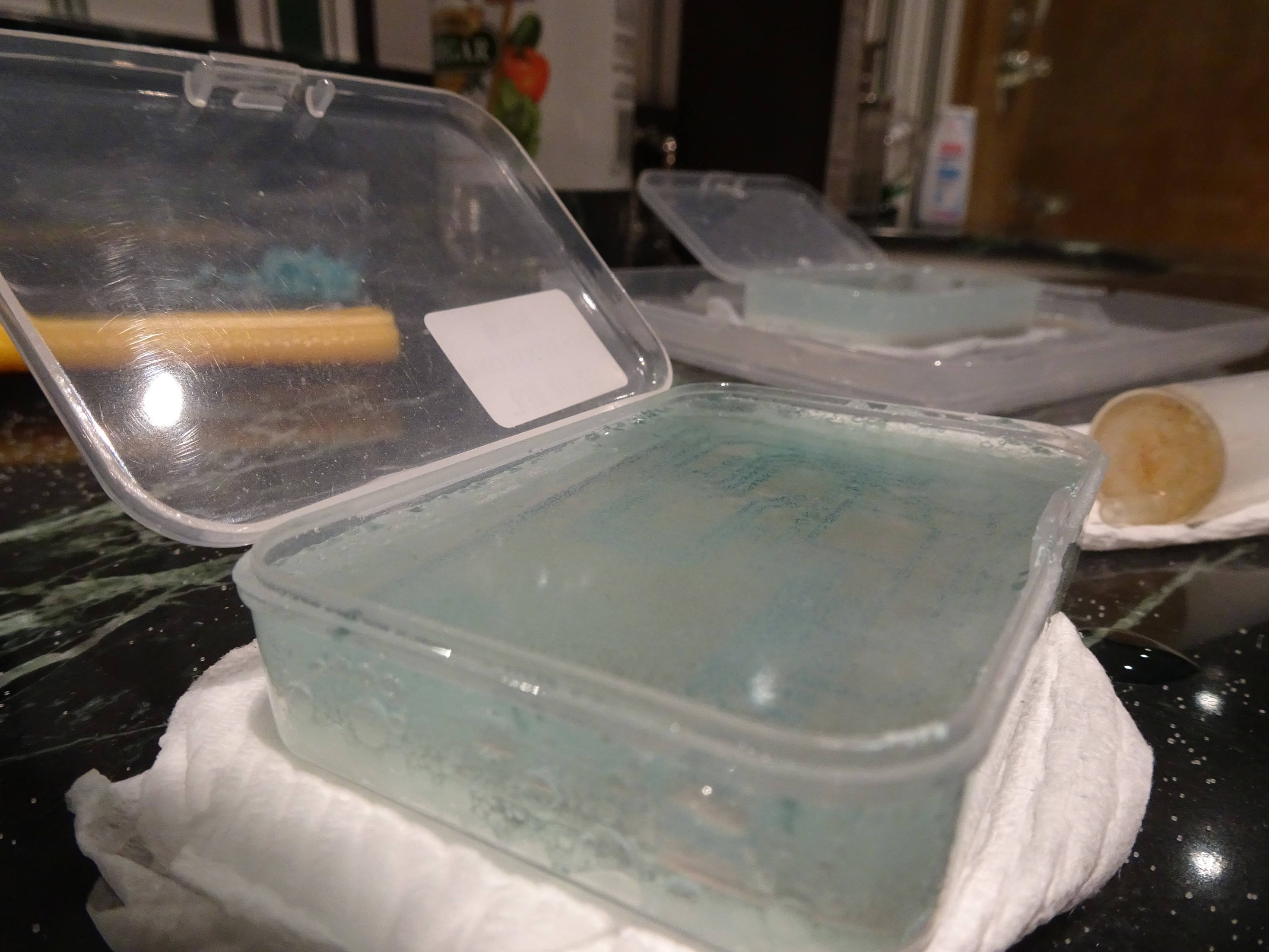
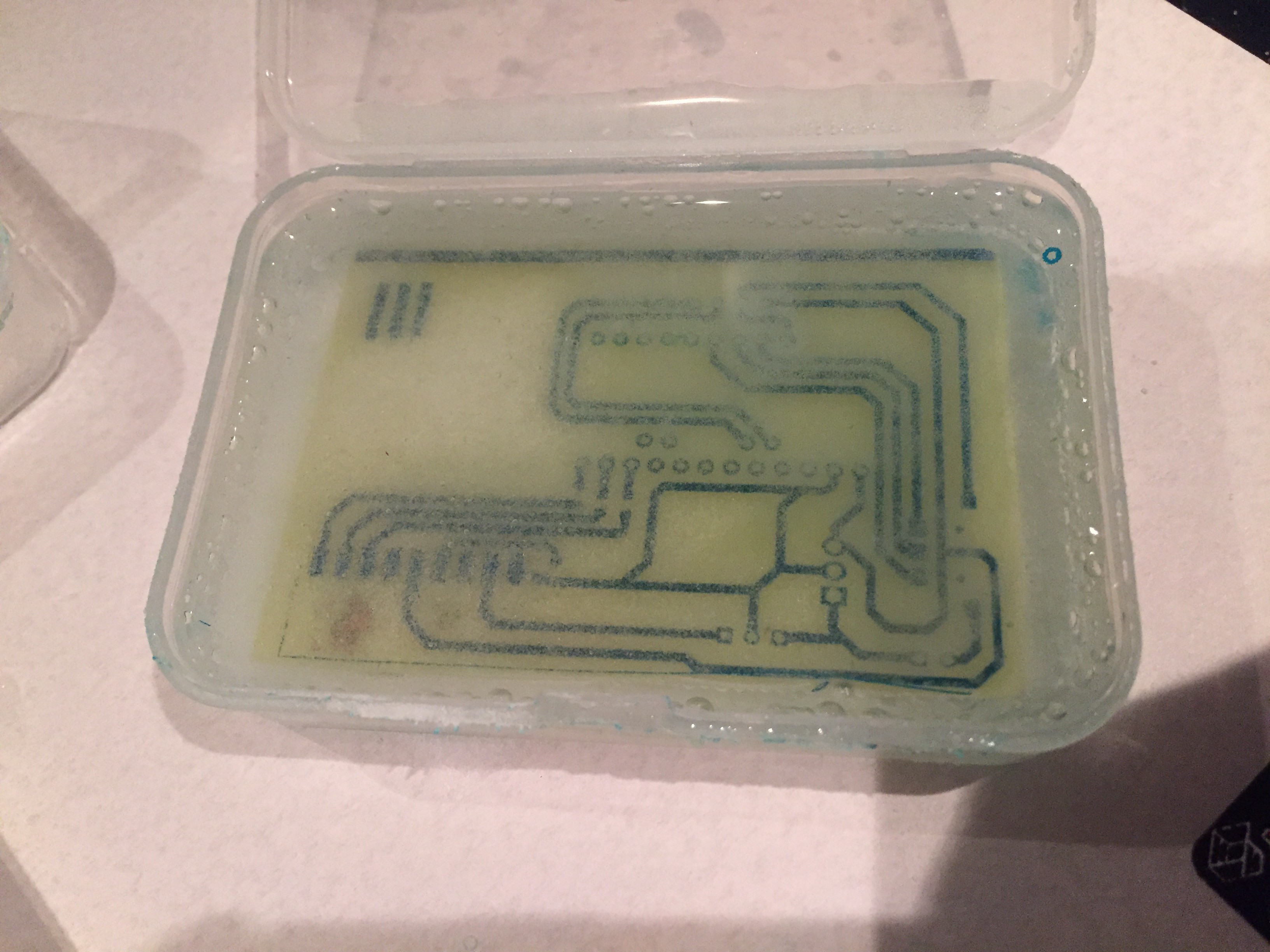
Following this attempt, I decided to try coating the PCB in a layer of spray paint, a method I had seen online a few times and thought was worth an attempt. This time the laser did a much better job of removing the coating and the design came out pretty good. Unfortunately the thin traces didn't quite make it as the spray paint tended to contract when vaporized. After I modified the spacing the PCB looked as though it would work perfectly-- and it probably would have in a common etchant like ferric chloride, but yet again I decided to experiment a little and attempted to etch my PCBs using a few common household ingredients, hydrogen peroxide, vinegar, and salt. Given that I was etching PCBs in my unventilated bathroom I didn't want to release bunch of noxious gases like chlorine into the enclosed environment by using an etchant like ferric chloride. This process, while much safer, comes with the cost that etching takes a fairly long time and after several hours, due to the weak bond between the spray paint and copper, the paint began peeling off the PCB and rendered the board useless.

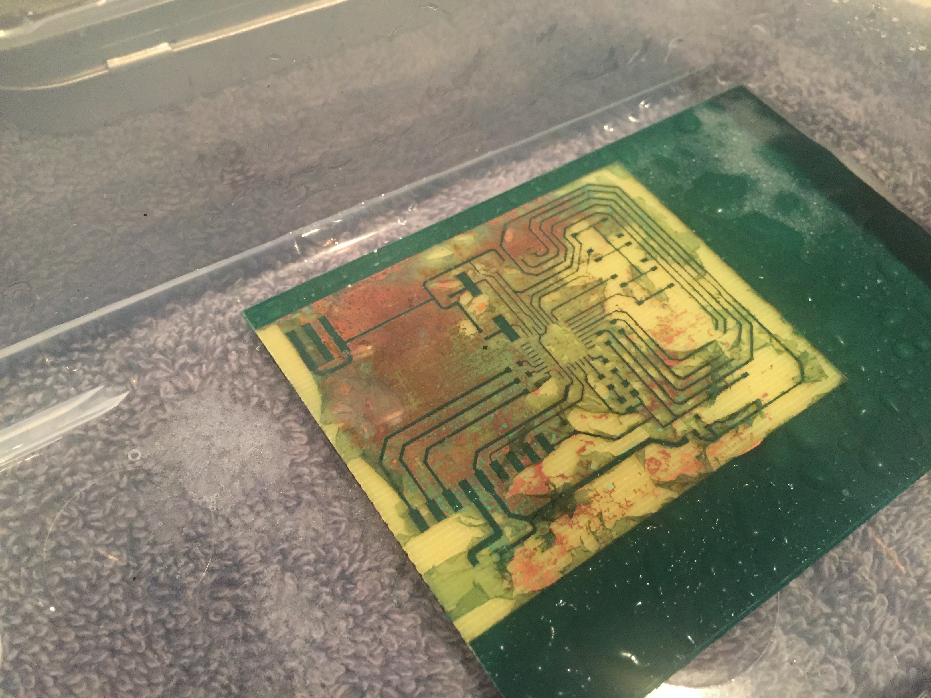
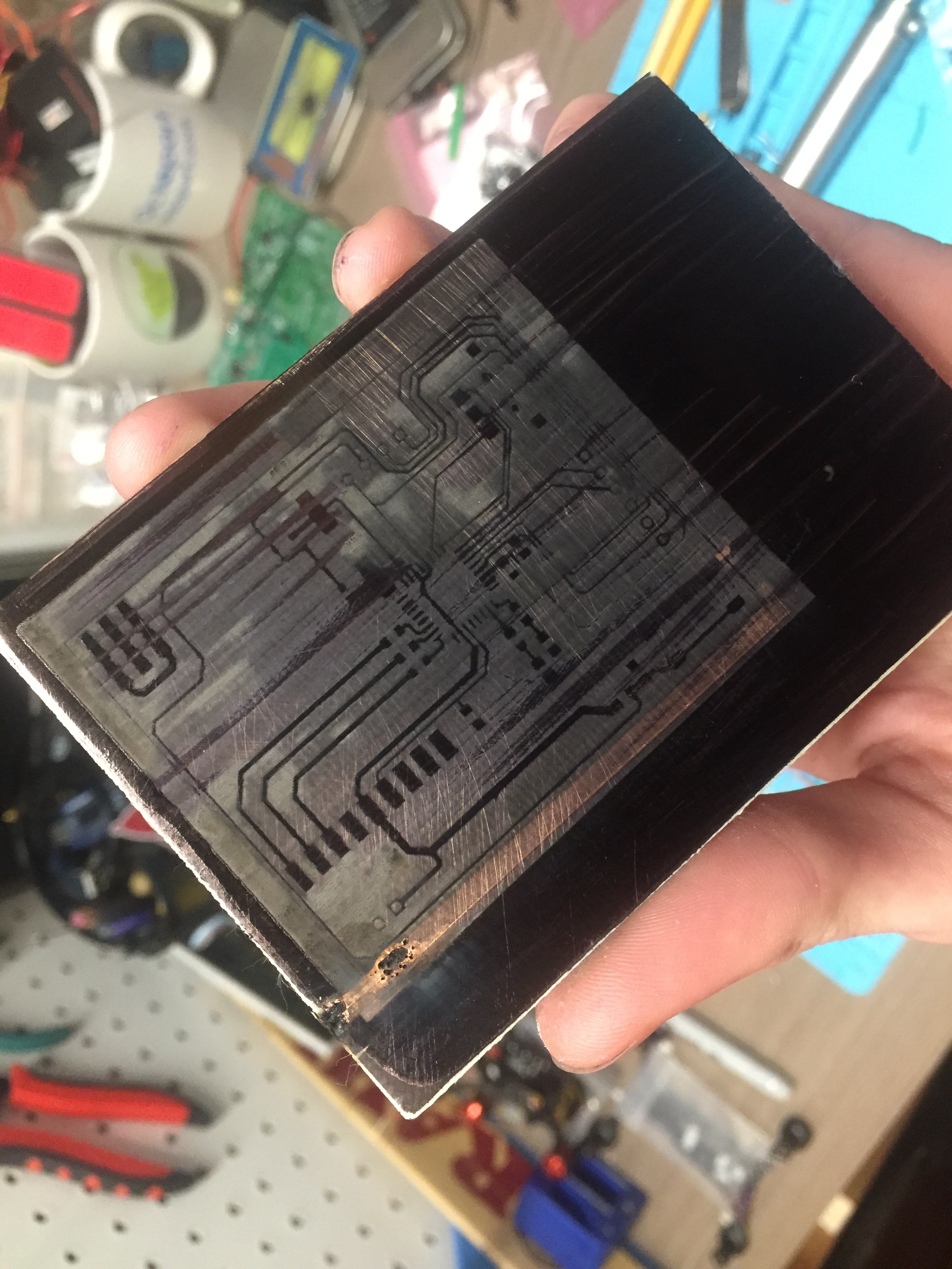
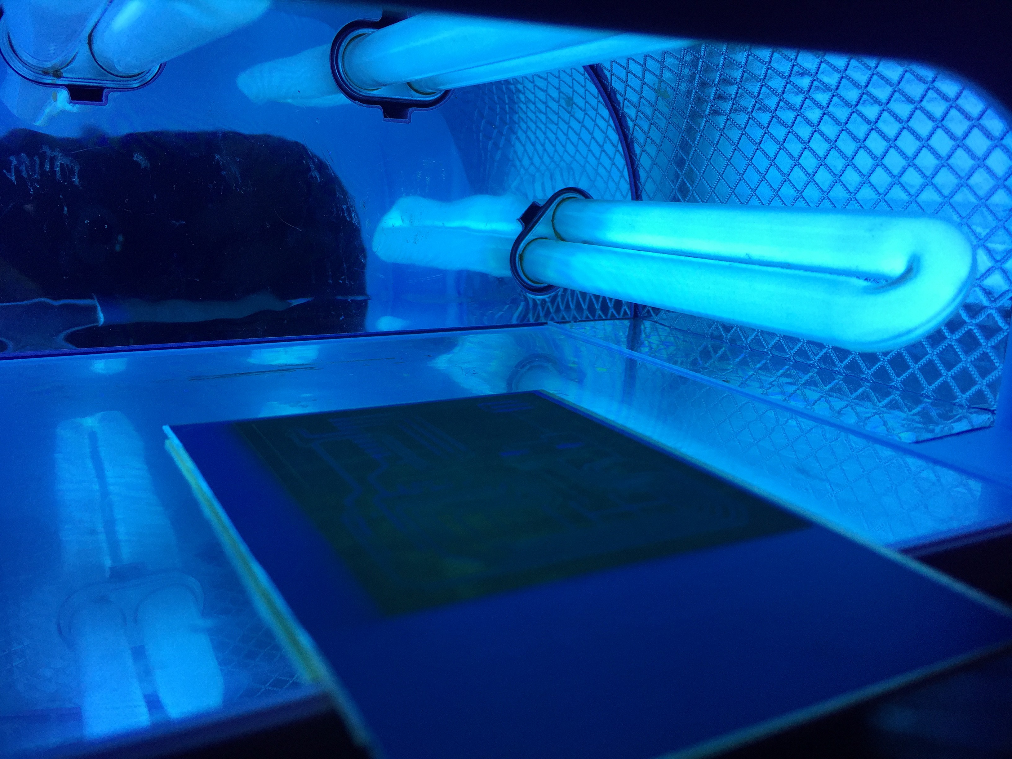
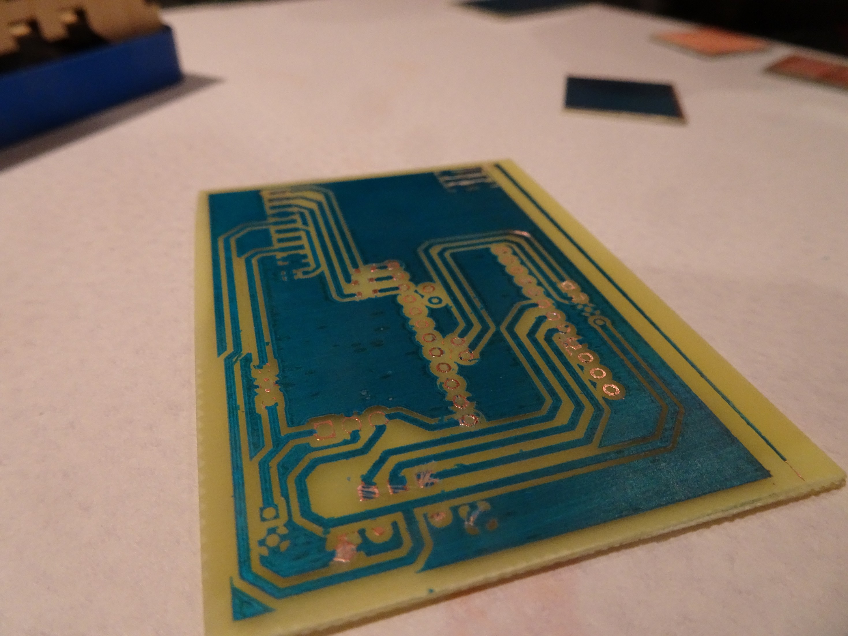
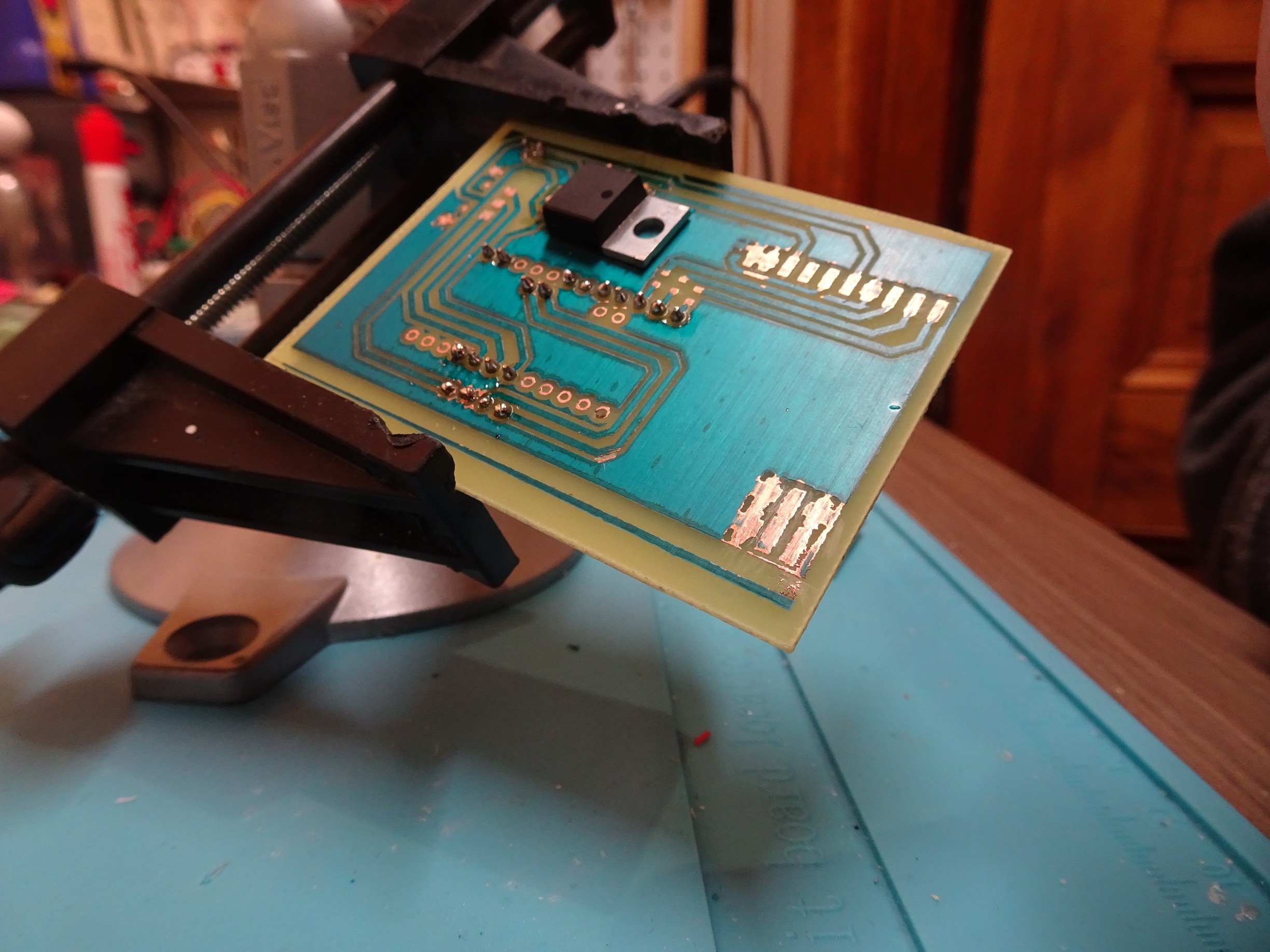
After this disappointment I decided to try a method I had used previously to etch a breakout board for an atmega IC with great success. Having acquired a few PCBs with pre-coated UV sensitive soldermask while in Shenzhen earlier this year, I broke out the UV lamp for my DLP 3D printer and got to experimenting with the boards. This time the laser etching worked out perfectly the first try and even after many hours in the PCB etchant, the soldermask stayed adhered to the board.
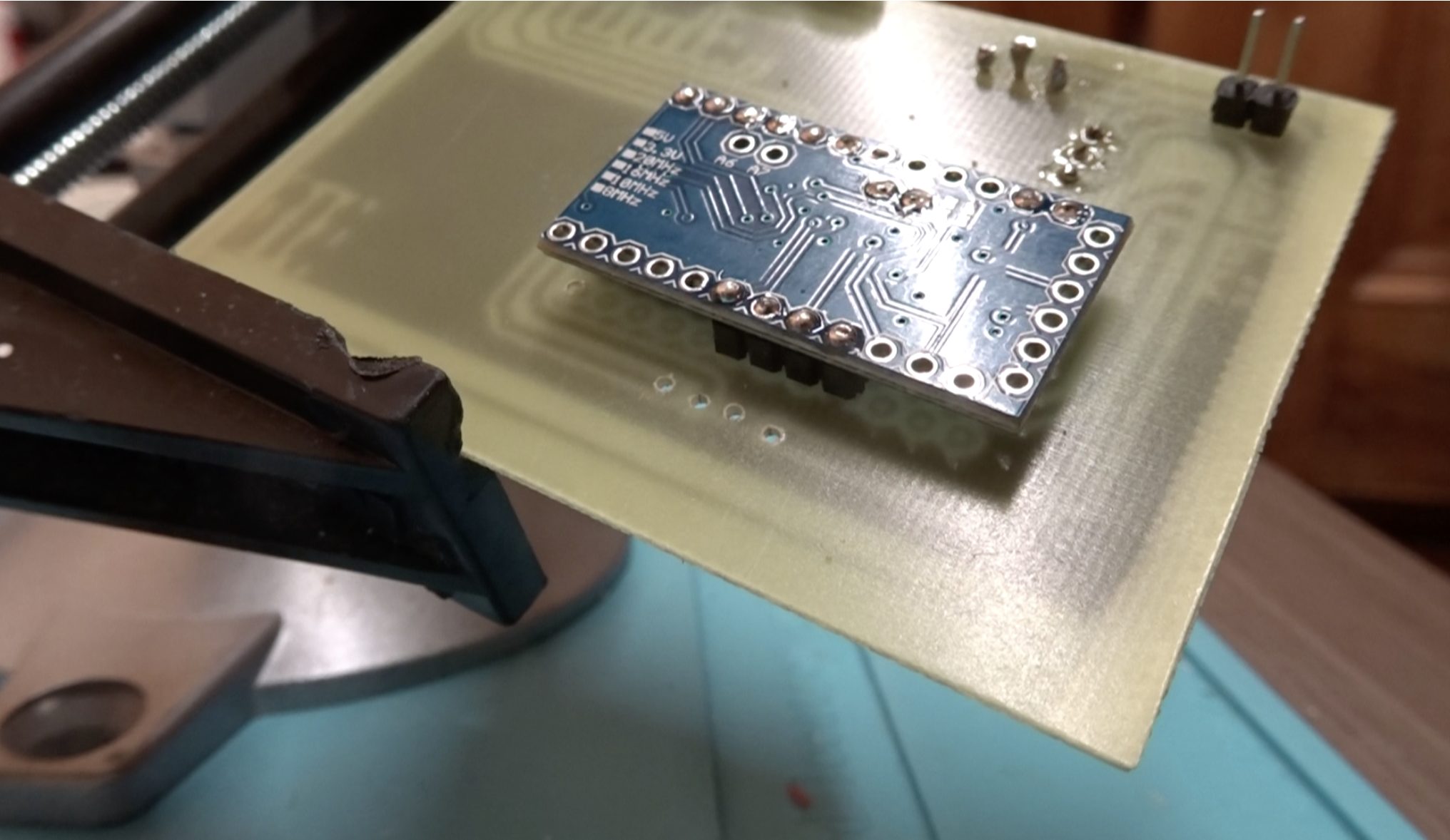
While I originally intended to integrate the ATMega directly into the PCB layout, designing the entire board on a single layer board turned out to be a little more challenging than I had bargained for. Rather than continue to mess around with the board's ever-growing complexity of wires connecting various ground planes and voltages lines, I decided to use a Sparkfun pro mini as the microcontroller instead and focus on getting the design to work properly before trying to overcomplicate the board. This ended up working out great and the PCB turned out even better than I could have hoped.
Once the PCB had finished the etching process, I used some acetone to remove the soldermask in the areas I would be soldering to and got to work assembling the board. Since I was using through-hole parts for many of the components on the PCB, I also had to drill the necessary holes for mounting the pro mini and voltage regulator.
Now that the copper has been etched and the holes have been drilled I can get to work assembling the board. Since the board was designed as a single layer PCB, the pro mini needs to be mounted upwards, but as I will be mounting the microcontroller on the underside the board the PCB needs to be soldered upside-down for proper connection.
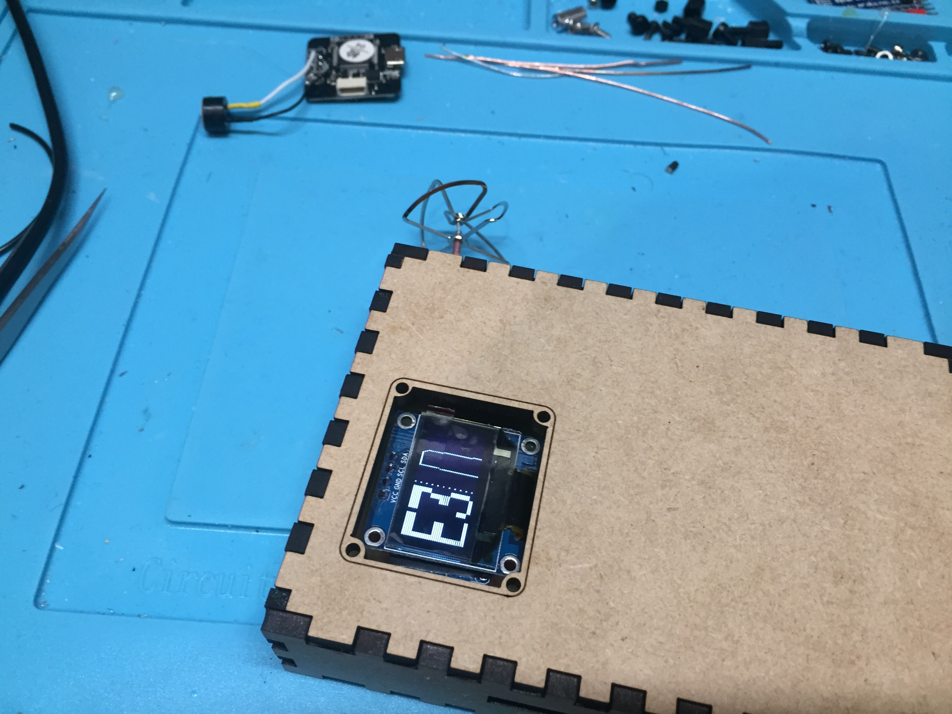
The OLED display gets stacked on top of the pro mini, so I covered underside of both PCBs with a layer of conformal coating and electrical tape for protection from short circuits. I designed this PCB for compatibility with the more popular 0.96" OLED displays available on eBay instead of the 1.3" variety which results in some of the displayed data getting cutoff. As the pinout is different for the 1.3" displays the OLED is not directly compatible with the prototype version of the PCB; however, I intend on fixing this in the PCB layout soon and will push the changes to GitHub when complete.


Finally I soldered on the resistors, the voltage regulator, selector switch, RX5808, and battery connector.
Ideally the board would be powered with 12V for the monitor; however, I decided to opt for a 2S lipo (8.4v peak) which works fine and allows for a smaller enclosure overall. In the future I plan on swapping this for a 1S lipo and integrating a 12V boost circuit and lipo charger into the board to get rid of the need for an external balance charger.
Once I had finished soldering on the various components, I was ready to begin testing. I loaded up the RX5808 Arduino code, disabled the option for diversity (as I am only using one receiver module in this design) attached a wire for the antenna and uploaded the program to the Arduino.
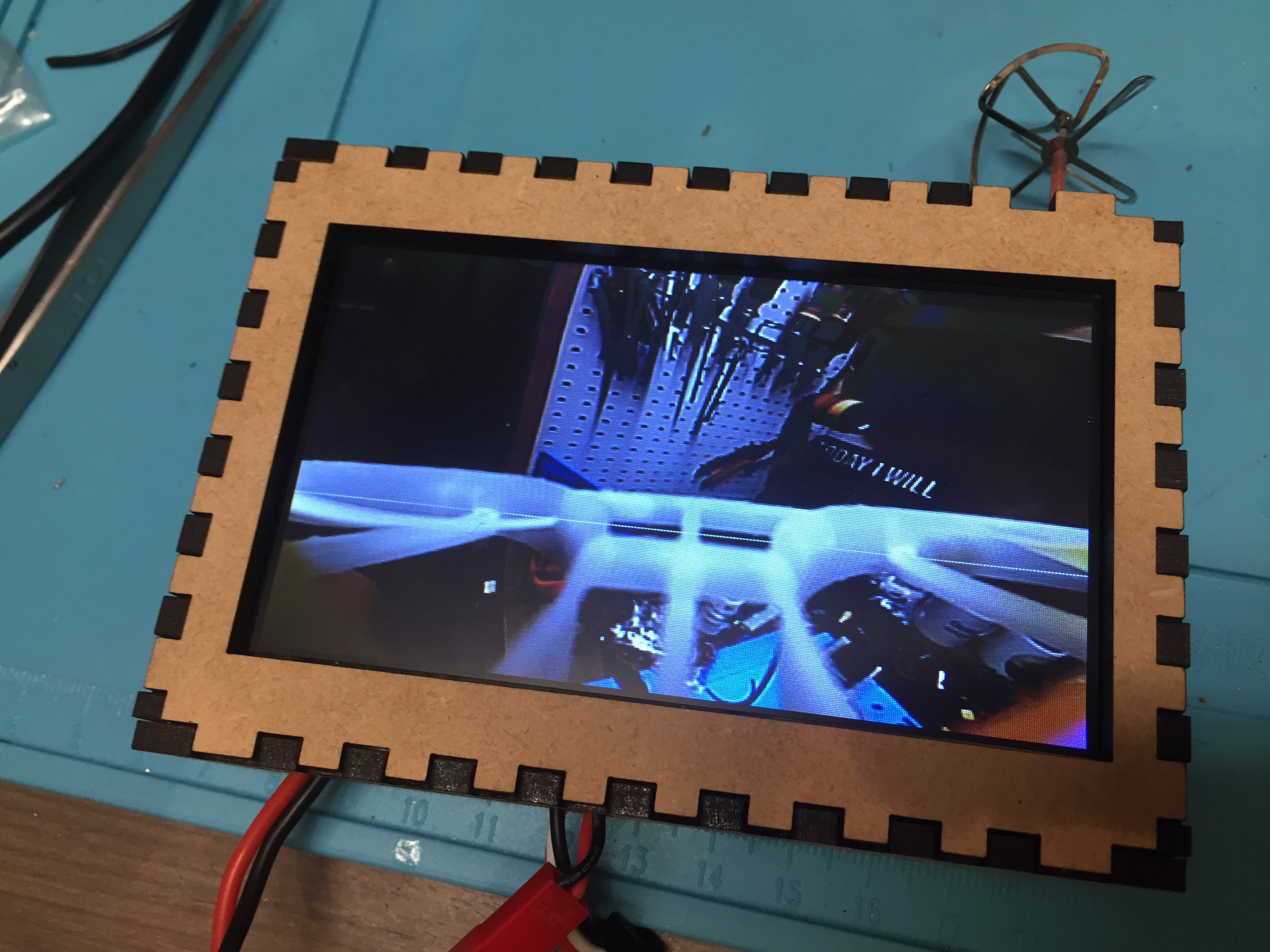
I plugged in the battery, connected the screen and...
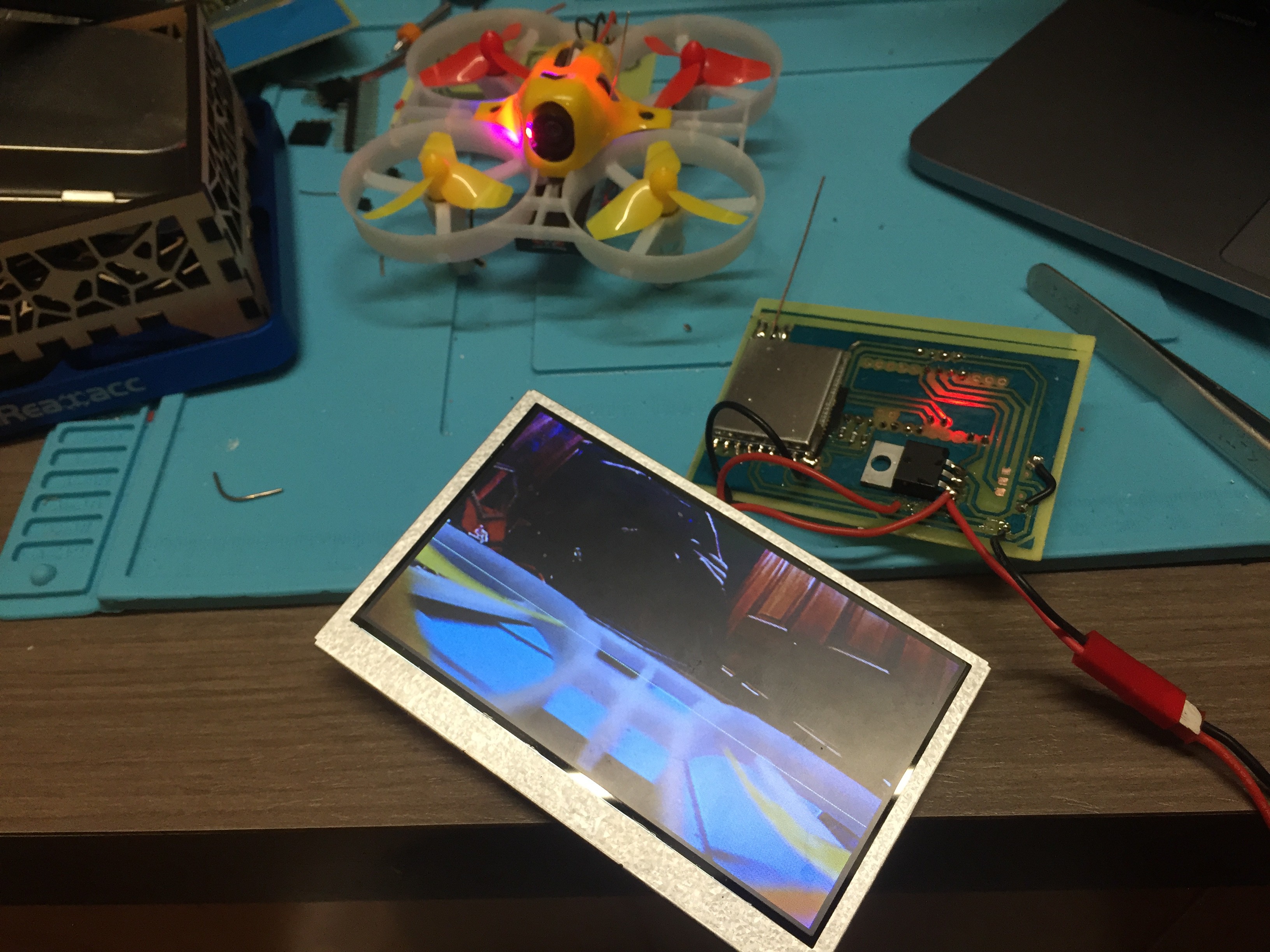
SUCCESS!
The video was displayed properly once I had navigated to the correct transmission channel using the OLED for reference.
Now that I knew the device was working, I could get to work doing some modifications and designing a sweet enclosure. I started with some draftboard and got to work making a simple case with a cutout for the displays and slots for the selector switch, battery, and antenna. Speaking of the antenna, I soon swapped out the monopole antenna for a higher quality circular polarized antenna that I purchased online, although in the future I think I will opt for a SMA connector for a little more customizability.

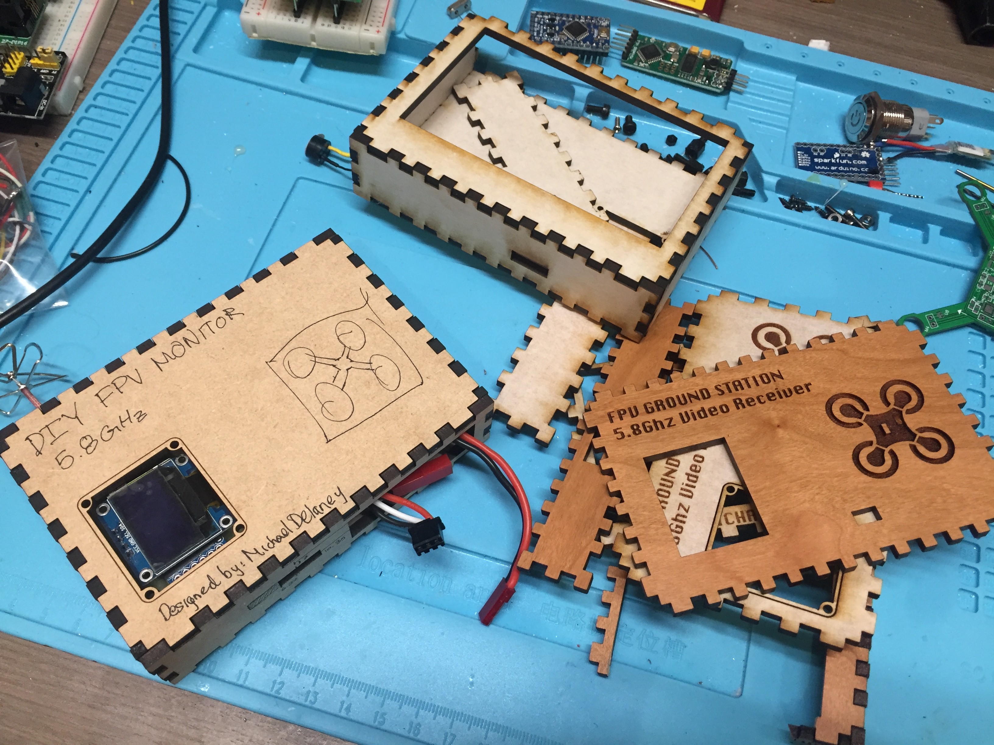
After a number of iterations and a lot of wasted wood, I ended up with this:


The result is an elegant and overall quite useful FPV monitor that I now bring with me whenever I fly. The finished product cost me around $40 to make, although with a cheap pro mini clone and inexpensive monitor it could be done for even less.
I will continue to make changes and upgrades to this design over the next little while and will update this project with the relevant changes as they come. If you liked this post and would like to stay up to date with more of my future updates and projects you can follow me on Instagram or subscribe on YouTube for more projects like this!
Instagram: http://instagram.com/3d_prints
YouTube: https://www.youtube.com/MichaelDelaney
(yea I know I haven't posted anything in a while, that will change soon!)